Input and Output
We have successfully run the various test cases in cpu-tests, but these test cases can only silently perform pure calculations. Recalling the first program hello we wrote in the programming course, at least it output one line of information. In fact, input and output are the basic means for computers to interact with the outside world. If you still remember that the full name of the BIOS program executed when the computer starts up is Basic Input/Output System, you will understand how important input and output is for computers. In real computers, input and output are accomplished by accessing I/O devices.
Devices and CPU
The working principle of devices is actually not mysterious. In the near future, you will see the Verilog code related to the keyboard controller module and VGA controller module in the digital circuit experiment. Oh, it turns out that these devices are also digital circuits! In fact, as long as some meaningful digital signals are sent to the device, the device will work according to the meaning of these signals. Isn't it like "the instructions of the program guide how the CPU works" to let some signals guide how the device works? That's exactly it! Devices also have their own status registers (equivalent to CPU registers) and their own functional units (equivalent to CPU arithmetic units). Of course, different devices have different functional units, for example, the keyboard has a component that converts the analog signal of the key press into a scan code, while the VGA has a component that converts the pixel color information into an analog signal for the display. The signal that controls the operation of the device is called a "command word", which can be understood as a "device instruction". The job of the device is to receive the command word and perform decoding and execution... You already know how the CPU works, all of this is too familiar to you.
Since devices are used for input and output, accessing devices is simply to obtain data from devices (input), such as getting key scan codes from the keyboard controller, or sending data to devices (output), such as writing color information of an image to the video memory. But what if the user doesn't type on the keyboard, or the user wants to adjust the screen resolution? This indicates that in addition to pure data reading and writing, we also need to control the devices: for example, we need to get the status of the keyboard controller to see if a key is currently pressed; or we need a way to query or set the resolution of the VGA controller. So, from the perspective of the program, accessing devices = reading data + writing data + controlling status.
We hope that the computer can control devices and make devices do what we want them to do. This task undoubtedly falls on the CPU. In addition to performing calculations, the CPU also needs to access devices and cooperate with them to complete different tasks. So from the CPU's perspective, what do these behaviors actually mean? Specifically, where should data be read from? Where should data be written to? How to query/set the status of the device? A fundamental question is, what is the interface between the CPU and devices?
The answer may be much simpler than you imagine: since devices also have registers, a simple way is to use the device's registers as the interface and let the CPU access these registers. For example, the CPU can read/write data from/to the device's data register to perform input/output; it can read the device's status from the device's status register to ask if the device is busy; or it can write a command word to the device's command register to modify the device's status.
So, how does the CPU access device registers? Let's first review how the CPU accesses its own registers: First, we assign a number to these registers, for example, eax is 0, ecx is 1... Then in the instructions, we reference these numbers, and there will be corresponding selectors on the circuit to select the corresponding register and perform read/write operations. Accessing device registers is similar: We can also assign numbers to the registers in the device that the CPU is allowed to access, and then reference these numbers through instructions. There may be some private registers in the device that are maintained by the device itself, they do not have such numbers, and the CPU cannot directly access them.
This is called the I/O addressing method, and these numbers are also called device addresses. There are two commonly used addressing methods.
Port I/O
One I/O addressing method is port-mapped I/O, where the CPU uses dedicated I/O instructions to access devices, and the device address is called the port number. Once we have the port number, we can specify the port number in the I/O instruction to know which device register to access. Most computers on the market are IBM PC compatible, and IBM PC compatible machines have specific regulations for allocating port numbers to common devices.
x86 provides the in and out instructions for accessing devices, where the in instruction is used to transfer data from the device register to the CPU register, and the out instruction is used to transfer data from the CPU register to the device register. An example is using the out instruction to send a command word to the serial port:
movl $0x41, %al
movl $0x3f8, %edx
outb %al, (%dx)
The above code sends the data 0x41 to the device register corresponding to port 0x3f8. After the CPU executes the above code, it will send the data 0x41 to one of the serial port's registers. After receiving it, the serial port will find that it needs to output the character A; but from the CPU's perspective, it doesn't care how the device processes the data 0x41, it will simply send 0x41 to port 0x3f8. In fact, the API and behavior of the device will be clearly defined in the corresponding documentation. In PA, we don't need to understand these details, we only need to know that driver developers can write corresponding programs to access devices by RTFM.
Does this feel familiar?
API, behavior, RTFM... That's right, we've seen another example of computer system design: The device exposes the interface of the device registers to the CPU, abstracting the complex behavior inside the device (even some characteristics of analog circuits). The CPU only needs to use this interface to access the device to achieve the desired functionality.
The idea of abstraction is pervasive in computer systems. As long as you understand the principles behind it, and add the RTFM skill, you can master all computer systems!
Memory-mapped I/O
Port-mapped I/O takes the port number as part of the I/O instruction, which is a simple method, but also its biggest drawback. The instruction set, in order to be compatible with already developed programs, can only be added but not modified. This means that the size of the I/O address space that port-mapped I/O can access is determined at the moment the I/O instruction is designed. The so-called I/O address space is actually the set of addresses of all accessible devices. As more and more devices and functions become more and more complex, port-mapped I/O with a limited I/O address space has gradually become unable to meet the demand. Some devices need the CPU to access a relatively large continuous storage space, such as the video memory of VGA, which requires a 3MB addressing range for a 1024x768 resolution with 24-bit color plus an Alpha channel. Hence, memory-mapped I/O (MMIO) was born.
This memory-mapped I/O addressing method is very ingenious, it addresses devices through different physical memory addresses. This addressing method "redirects" the access to a portion of physical memory to the I/O address space, when the CPU attempts to access this portion of physical memory, it actually ends up accessing the corresponding I/O device, but the CPU is unaware of this. After that, the CPU can access devices through ordinary memory access instructions. This is also the great advantage of memory-mapped I/O: The physical memory address space and the CPU's bit width will continue to grow, and memory-mapped I/O never needs to worry about the I/O address space being exhausted. In principle, the only drawback of memory-mapped I/O is that the CPU cannot directly access the physical memory that is mapped to the I/O address space through normal channels. However, as computers have developed, the only drawback of memory-mapped I/O has become less and less noticeable: Modern computers are already 64-bit computers, with 48 physical address lines, meaning the physical address space is as large as 256TB, carving out a 3MB address space for video memory is just a drop in the bucket.
Precisely because of this, memory-mapped I/O has become the mainstream I/O addressing method for modern computers: RISC architectures only provide memory-mapped I/O addressing, and mainstream devices such as PCI-e, network cards, and x86's APIC all support access through memory-mapped I/O.
As RISC architectures, both mips32 and riscv32 use the memory-mapped I/O addressing method. For x86, an example of memory-mapped I/O is the physical address range [0xa1000000, 0xa1800000) in NEMU. This physical address range is mapped to the video memory inside the VGA, reading and writing to this physical address range is equivalent to reading and writing data to the VGA video memory. For example:
memset((void *)0xa1000000, 0, SCR_SIZE);
This will zero out a screen-sized data in the video memory, i.e., write black pixels to the entire screen, effectively clearing the screen. We can see that the programming model of memory-mapped I/O is exactly the same as normal programming: Programmers can directly access I/O devices as if they were memory. This feature is also deeply loved by driver developers.
Understanding the volatile keyword
Perhaps you've never heard of the volatile keyword in C, but it has existed since the birth of C. The volatile keyword has a very special purpose, which is to prevent the compiler from optimizing the corresponding code. You should try to experience the effect of volatile by writing the following code on GNU/Linux:
void fun() {
  extern unsigned char _end;  // What is _end?
  volatile unsigned char *p = &_end;
  *p = 0;
  while(*p != 0xff);
  *p = 0x33;
  *p = 0x34;
  *p = 0x86;
}
Then compile the code using
-O2. Try removing thevolatilekeyword from the code, recompile using-O2, and compare the differences in the disassembly results before and after removingvolatile.You may be puzzled, isn't code optimization a good thing? Why does such a weird thing as
volatileexist? Think about it, if the address thatppoints to in the code is eventually mapped to a device register, what problems might removingvolatilecause?
Input/Output from a State Machine Perspective
In PA1, we mentioned that both computers and programs can be viewed as state machines, and the state of this state machine can be represented as S = <R, M>, where R is the state of the registers, and M is the state of the memory. After adding input/output functionality to the computer, how should we understand the behavior of input/output?
We can divide the device into two parts, one part is the digital circuit. We have briefly introduced some functions of device controllers, for example, our CPU can read key information from the keyboard controller. Since it is a digital circuit, we can treat the sequential logic circuit within it as the state D of the digital circuit part of the device. However, D is somewhat special, the computer can only access and modify D through port I/O instructions or memory access instructions for memory-mapped I/O.
Interestingly, the other part of the device is the analog circuit, which can also change D. For example, the keyboard determines whether a key is pressed by checking the capacitance change at the key position, if so, it will write the key information to the register of the keyboard controller. Whether the capacitance at the key position changes or not is determined by whether the user presses the key in the physical world. So we say that the device is a bridge connecting the computer and the physical world.
  State machine               |           Out side of state machines
  S = <R, M>                  |                D
  computer/program  <----I/O instruction----> device <----analog circuit----> physical world
                              |
                              |
Modeling the state and behavior of devices is a very difficult task, not only are the behaviors of devices themselves diverse, but the state of devices is also constantly influenced by the physical world. Therefore, when extending the behavior of the state machine model, we do not consider adding D to S, but only model the behavior of input/output-related instructions:
- When executing ordinary instructions, the state machine transitions according to the TRM model
- When executing device output-related instructions (such as the
outinstruction in x86 or the MMIO write instruction in RISC architectures), the state machine remains unchanged except for updating the PC, but the state of the device and the physical world will change accordingly - When executing device input-related instructions (such as the
ininstruction in x86 or the MMIO read instruction in RISC architectures), the state machine transition will "branch": the state machine no longer has a unique new state like in the TRM, which new state the state machine will transition to will depend on the state of the device when executing this instruction
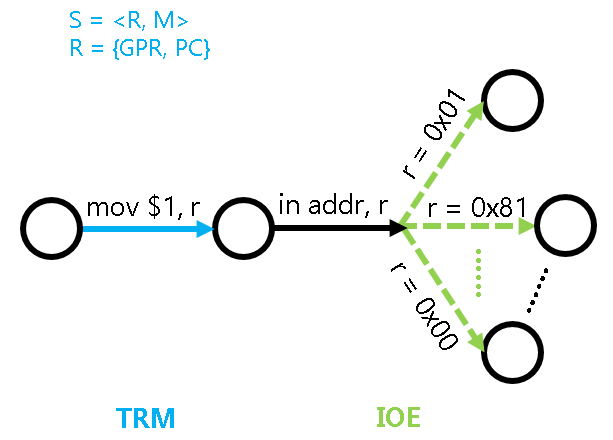
For example, in the figure above, the program is about to execute the instruction in addr, r, this instruction will read data from the device address addr into the CPU register r. Let's assume that this device address corresponds to a keyboard controller, after executing this instruction, the value in r may be 0x01, indicating that it has read the information "key with scan code 1 is pressed"; it may also be 0x81, indicating that it has read the information "key with scan code 1 is released"; or it may be 0x0, indicating that there is no key information. This uncertain state transition will affect the subsequent execution of the program, for example, a game may decide how to respond based on the key information read, but it is not difficult to understand that how the game responds is implemented through ordinary computational instructions in the TRM, and has nothing to do with input/output.
This extended state machine model tells us from a microscopic perspective that the input and output of devices are all done through data interaction with the CPU registers. The impact of input/output on the program is only reflected in an uncertain state transition during input, which is basically all there is to input/output from the program's perspective.
Input/Output through Memory Data Interaction
We know that S = <R, M>, and the port I/O and memory-mapped I/O introduced above all perform data interaction through the register R. Naturally, we can consider whether there is an input/output method that performs data interaction through memory M.
Actually, there is such a method called DMA. To improve performance, most complex devices generally have DMA functionality. However, the devices in NEMU are relatively simple, so we will not go into the details of DMA.
Input/Output in NEMU
The NEMU framework code has already provided device-related code in the nemu/src/device/ directory,
Mapping and I/O Methods
NEMU implements two I/O addressing methods: port-mapped I/O and memory-mapped I/O. However, whether it is port-mapped I/O or memory-mapped I/O, their core is mapping. Naturally, we can unify these two by managing the mapping.
Specifically, the framework code defines a structure type IOMap (defined in nemu/include/device/map.h) for mapping, including the name, start and end addresses of the mapping, the target space of the mapping, and a callback function. Then in nemu/src/device/io/map.c, the management of mapping is implemented, including the allocation and mapping of the I/O space, as well as the access interface for mapping.
Among them, map_read() and map_write() are used to map the address addr to the target space indicated by map, and perform access. During access, the corresponding callback function may be triggered to update the state of the device and the target space. Since NEMU is a single-threaded program, it can only simulate the operation of the entire computer system serially, and the callback function (callback) provided by the device will only be called when performing I/O read/write. Based on these two APIs, we can easily implement the simulation of port-mapped I/O and memory-mapped I/O.
nemu/src/device/io/port-io.c is the simulation of port-mapped I/O. The add_pio_map() function is used to register a port-mapped I/O mapping relationship for device initialization. pio_read() and pio_write() are the port I/O read/write interfaces facing the CPU, they will eventually call map_read() and map_write() to access the I/O space registered through add_pio_map().
The simulation of memory-mapped I/O is similar, paddr_read() and paddr_write() will determine whether the address addr falls in the physical memory space or the device space. If it falls in the physical memory space, it will access the real physical memory through pmem_read() and pmem_write(); otherwise, it will access the corresponding device through map_read() and map_write(). From this perspective, memory and peripherals are no different from the CPU's point of view, they are just byte-addressable objects.
Devices
NEMU implements seven devices: serial port, clock, keyboard, VGA, sound card, disk, and SD card, among which the disk will be introduced at the end of PA, and the SD card will not be involved in PA. To simplify the implementation, these devices are all non-programmable, and only the functions used in NEMU are implemented. To enable device simulation, you need to select the relevant option in menuconfig:
[*] Devices --->
After recompiling, you will see that a new window will pop up when running NEMU, which is used to display the VGA output (see below). Note that the prompt (nemu) displayed in the terminal is still waiting for user input, and the window does not display any content at this time.
NEMU uses the SDL library to implement device simulation, and nemu/src/device/device.c contains code related to the SDL library. The init_device() function mainly performs the following tasks:
- Call
init_map()for initialization. - Initialize the above devices, and during the initialization of VGA, some SDL-related initialization work will also be performed, including creating windows, setting display modes, etc.
- Then it will perform initialization work related to the timer (alarm). The timer function will not be used until the end of PA4, so it can be ignored for now.
On the other hand, cpu_exec() will call the device_update() function after executing each instruction. This function first checks whether a certain amount of time has elapsed since the last device update, if so, it will attempt to refresh the screen, and further check whether any keys have been pressed/released, and whether the X button of the window has been clicked; otherwise, it will return directly to avoid checking too frequently, because the above events occur at a very low frequency.
Abstracting Input/Output into IOE
The specific implementation of device access is architecture-dependent. For example, NEMU's VGA memory is located in the physical address range [0xa1000000, 0xa1080000), but for native programs, this is an inaccessible illegal range. Therefore, native programs need to implement similar functionality in other ways. Naturally, this architecture-dependent functionality of device access should be included in AM. Unlike TRM, device access provides input and output functionality for computers, so we categorize them into a new API called IOE (I/O Extension).
How can we abstract device access across different architectures into a unified API? Recall that from the program's perspective, accessing a device essentially wants to do the following: device access = read data + write data + control state. Furthermore, controlling the state is essentially an operation of reading/writing device registers, so device access = read/write operation.
Yes, it's that simple! So IOE provides three APIs:
bool ioe_init();
void ioe_read(int reg, void *buf);
void ioe_write(int reg, void *buf);
The first API is for performing IOE-related initialization operations. The latter two APIs are used to read content from the register numbered reg into the buffer buf, and to write the content of the buffer buf into the register numbered reg, respectively. Note that the reg register here is not the device register discussed earlier, because the numbering of device registers is architecture-dependent. In IOE, we want to adopt an architecture-independent "abstract register". This reg is actually a function number, and we agree that the meaning of the same function number is also the same across different architectures, thus achieving the abstraction of device registers.
abstract-machine/am/include/amdev.h defines the "abstract register" numbers and corresponding structures for common devices. These definitions are architecture-independent, and each architecture needs to follow these definitions (conventions) when implementing its own IOE API. For convenient access to these abstract registers, klib provides the io_read() and io_write() macros, which further encapsulate the ioe_read() and ioe_write() APIs, respectively.
Particularly, as a platform, NEMU's device behavior is ISA-independent. Therefore, we only need to implement one IOE in the abstract-machine/am/src/platform/nemu/ioe/ directory, which can be shared by all architectures on the NEMU platform. Among them, abstract-machine/am/src/platform/nemu/ioe/ioe.c implements the three IOE APIs mentioned above. Both ioe_read() and ioe_write() index to a handler function based on the abstract register number and then call it. The specific functionality of the handler function is related to the register number. Next, we will introduce the functionality of each device in NEMU one by one.
Serial Port
The serial port is the simplest output device. nemu/src/device/serial.c simulates the functionality of the serial port. Most of its functionality is also simplified, leaving only the data register. During serial port initialization, it registers an 8-byte port at 0x3F8 and an 8-byte MMIO space at 0xa00003F8, both of which are mapped to the serial port's data register. Since NEMU simulates the operation of a computer system in series, the serial port's status register can always be in an idle state; whenever the CPU writes data to the data register, the serial port will send the data to the host's standard error stream for output.
In fact, in $ISA-nemu, the putch() function we mentioned earlier is output through the serial port. However, AM puts putch() in TRM instead of IOE, which seems a bit strange. Indeed, the most primitive TRM proposed in computational theory does not include the ability to output, but for a real computer system, output is a basic functionality. Without output, the user would not even know what the program is doing. Therefore, in AM, the addition of putch() gives TRM the ability to output characters, and the extended TRM is closer to a practical machine rather than just a mathematical model for computation.
The putch() in abstract-machine/am/src/platform/nemu/trm.c will output the character to the serial port. If you choose x86, to allow the program to use the serial port for output, you also need to implement port-mapped I/O in NEMU.
Run Hello World
If you choose x86, you need to implement the in and out instructions. Specifically, you need to RTFSC, and then correctly call pio_read() and pio_write() in the implementation of the in and out instructions. If you choose mips32 or riscv32, you don't need to implement additional code, because the NEMU framework code already supports MMIO.
After implementation, enter the following in the am-kernels/kernels/hello/ directory:
make ARCH=$ISA-nemu run
If your implementation is correct, you will see the program output some information to the terminal (be careful not to let the output be overwhelmed by debug information).
It should be noted that this hello program is at a different level of abstraction from the first hello program we wrote in the programming course: this hello program can be said to run directly on bare metal, and can output directly to devices (serial ports) above the AM abstraction; while the hello program we wrote in the programming course is above the operating system, and cannot directly operate devices, but can only output through services provided by the operating system, and the output data has to go through many layers of abstraction before reaching the device layer. We will further experience the role of the operating system in PA3.
Devices and DiffTest
From the state machine perspective, executing an input instruction causes the state transition of the state machine to become non-unique, with the new state depending on the state of the device. Since the behavior of devices in NEMU is customized by us and is not exactly the same as the behavior of standard devices in REF (for example, the serial port in NEMU is always ready, but the serial port in QEMU may not be), this causes the result of executing input instructions in NEMU to be different from REF. To allow DiffTest to work properly, the framework code calls the difftest_skip_ref() function during device access (see the find_mapid_by_addr() function defined in nemu/include/device/map.h) to skip checking against REF.
In AM, the main() function allows for a string argument, which is specified by mainargs and passed to the main() function by the AM runtime environment for use by the AM program. The specific method of passing the argument is architecture-dependent. For example, you can provide a string argument when running hello:
make ARCH=$ISA-nemu run mainargs=I-love-PA
This argument will be output verbatim by the hello program.
Understanding mainargs
Please RTFSC to understand how this argument is passed from the make command to the hello program. $ISA-nemu and native use different passing methods, both of which are worth understanding.
Implement printf
With putch(), we can now implement printf() in klib.
You have already implemented sprintf(), which is very similar in functionality to printf(), meaning there will be a lot of duplicated code between them. You have already seen the drawbacks of the copy-paste programming habit. Think about how to implement them concisely.
After implementing printf(), you can use output debugging in AM programs.
Run alu-tests
We have ported a program specifically for testing various C language operations in the am-kernels/tests/alu-tests/ directory. After implementing printf(), you can run it. The compilation process may take about 1 minute.
Clock
With a clock, programs can provide time-related experiences, such as frame rates and program speed. nemu/src/device/timer.c simulates the functionality of the i8253 timer. Most of the timer's functionality has been simplified, leaving only the "initiating clock interrupt" function (which we will not use for now). At the same time, a custom clock has been added. During initialization, the i8253 timer registers an 8-byte port at 0x48 and an 8-byte MMIO space at 0xa0000048, both of which are mapped to two 32-bit RTC registers. The CPU can access these two registers to obtain the current time represented in 64 bits.
Why not set a 64-bit RTC register?
We want the design of devices to be decoupled from the CPU, so that devices can work with any CPU architecture they are connected to. However, a 32-bit CPU cannot access a 64-bit device register at once, so splitting a 64-bit function into two 32-bit device registers can support both 32-bit and 64-bit CPUs.
abstract-machine/am/include/amdev.h defines two abstract registers for clock functionality:
AM_TIMER_RTC, AM Real Time Clock (RTC), which can read the current year, month, day, hour, minute, and second. Not used in PA for now.AM_TIMER_UPTIME, AM system uptime, which can read the number of microseconds since the system started.
RTC - Real-Time Clock
RTC refers to a clock whose elapsed rate is consistent with real time, allowing users to measure a period of time based on the RTC. According to this definition, both of the above AM abstract registers are RTCs, but they have different emphases: AM_TIMER_RTC emphasizes that the read time is completely consistent with real time, while AM_TIMER_UPTIME emphasizes the time elapsed since the system started, i.e., counting from 0.
Although the device register in NEMU is also called RTC, it does not need to be implemented as AM_TIMER_RTC to support the AM_TIMER_UPTIME functionality.
Implement IOE
Implement the AM_TIMER_UPTIME functionality in abstract-machine/am/src/platform/nemu/ioe/timer.c. There is some input/output related code available for you to use in abstract-machine/am/src/platform/nemu/include/nemu.h and abstract-machine/am/src/$ISA/$ISA.h.
After implementation, run the real-time clock test in am-kernel/tests/am-tests under $ISA-nemu. If your implementation is correct, you will see the program output a line to the terminal every second. Since we have not implemented AM_TIMER_RTC, the test will always output January 0, 1900, 0:00:00, which is normal behavior and can be ignored.
Do not run IOE-related tests when linking to klib on native
The IOE on native is implemented based on the SDL library, which assumes that the behavior of common library functions will conform to the glibc standard. However, our own implementation of klib usually cannot meet this requirement. Therefore, __NATIVE_USE_KLIB__ is only for testing the klib implementation, and we do not require all programs to run correctly when __NATIVE_USE_KLIB__ is defined.
RTFSC to understand all the details as much as possible
Many students often feedback that they have little experience in reading code and have not seen how good code is written. On the other hand, these students only care about where to write code when doing experiments, and they think they have completed the experiment once they have written the code, and thus feel that other code and experiment content are irrelevant and are unwilling to spend time reading it.
Students with this attitude are actually actively giving up the opportunity to practice their abilities. If you truly want to learn, you should not think "this file seems unnecessary to read, I don't care about it", but should actively think "this is the result of the program running, let me read the code to see how it is actually written". In fact, there are many treasures in the framework code, even in the test code. Reading them not only allows you to understand the specific behavior of these tests, but you will also learn how programs should use the AM API, and even the coding style is worth learning.
Therefore, let's leave it to you to RTFSC on how to run the real-time clock test.
See how fast NEMU runs
With the clock, we can now test how fast a program runs, and thus test the computer's performance. Try running the following benchmarks in NEMU (they are sorted by program complexity and are all in the am-kernel/benchmarks/ directory; also, when running the benchmarks, please turn off NEMU's watchpoints, trace, and DiffTest, and uncheck Enable debug information in menuconfig and recompile NEMU to get a more realistic score):
- dhrystone
- coremark
- microbench
After successful execution, a score will be output. For microbench, the score is based on an i9-9900K @ 3.60GHz processor as a reference, where 100000 represents performance equivalent to the reference machine, and 100 represents performance one-thousandth of the reference machine. In addition to comparing with the reference machine, you can also compare with your classmates. If you compile the above benchmarks to native, you can also compare the performance of native.
Additionally, microbench provides four different test sets, including test, train, ref, and huge. You can first run the test set, which can finish running relatively quickly, to check the correctness of your NEMU implementation, and then run the ref set to measure performance. Please read the README for specific instructions on how to run them.
Furthermore, the huge set is generally used for testing on real machines, and it takes a long time to run on NEMU, so we do not require you to run it.
Score reference
Running the ref input of microbench on a real machine with the RISC-V NEMU (developed following the regular PA process, without optimization) yields a score of around 300~500. If running in a virtual machine, the score will be lower. If the score is too low when running in a virtual machine (e.g., only a few points), you can try changing the timer used by NEMU from gettimeofday() to clock_gettime() in menuconfig:
Miscellaneous
      Host timer (clock_gettime)
If the score improves significantly after recompiling NEMU, the low performance of gettimeofday() may be related to the clock source (clocksource). You can try adjusting it by referring to this post, or by restarting the virtual machine or real machine (some students have reported that restarting can solve the problem), and then switch back to gettimeofday() and compare the performance.
How to debug complex programs
As programs become more and more complex, debugging becomes increasingly difficult, and bugs can become increasingly strange. This is almost a pain that every student working on PA must experience: the ability you have trained in the program design course is simply not enough to allow you to write correct programs. But after you graduate, you still need to face projects with tens of thousands or even hundreds of thousands of lines of code, compared to which PA is just a small toy.
In PA, we let you face these pains, ultimately hoping that you will understand the true debugging method, so that you can face larger projects in the future:
- RTFSC. This is to let you understand how all the details happen, these details will become useful clues when debugging, because: Only when you understand what is "correct" will you know what is "wrong"; The clearer your understanding of "correct", the deeper your understanding of "wrong" will be.Therefore, when you encounter a bug and feel helpless, completely unable to understand how this bug might have occurred, it is almost always because you were previously unwilling to RTFSC, thinking it didn't matter if you didn't read it, resulting in you having no usable clues to help you analyze the bug.
- Use the right tools. The bugs you encounter are strange and varied, but there are always ways to help you solve them efficiently. We have introduced a lot of tools and methods in the lecture notes, and they all have their own applicable situations and limitations.Therefore, if you have an initial guess about the cause of a bug, but have no idea how to go about debugging it, it is almost always because you have not mastered these tools and methods proficiently, resulting in your inability to choose an appropriate debugging plan based on the actual situation, or even because you completely ignored them, thinking it didn't matter if you didn't understand them. For example, we have already suggested an efficient way to deal with segmentation faults in one of the optional questions, if you don't know what to do when you encounter a segmentation fault, and you ignore the above suggestion, you have probably wasted a lot of unnecessary time.
The skills practiced in PA are interconnected, and when you think you can save time by "not carefully reading the code/lecture notes/manuals", you will inevitably have to pay more for it in the future: when bugs come, the debt owed will have to be repaid.
RTFSC to understand all details
Regarding the implementation of AM_TIMER_UPTIME, we have planted some small pitfalls in the framework code, If you have not fixed the related issues, you may encounter incorrect scoring when running the benchmark. This is to force everyone to seriously RTFSC and understand all the details of the program execution process: When the benchmark reads the clock information, what exactly happens in the entire computer system? Only in this way can you debug the clock-related bugs correctly.
NEMU and language interpreters
In microbench, there is a test project called bf, which is an interpreter for the Brainf**k language. The Brainf**k language is very simple, it only has 8 instructions, and doesn't even have the concept of variables, so it is very close to machine language. Students who are interested can read the code of bf.c, you will find that such a simple language interpreter and the seemingly complex NEMU are still similar in principle.
Complete first, then perfect - Suppress the urge to optimize code
The design process of a computer system can be summarized into two things:
- Design a functionally correct and complete system (complete first)
- Based on point 1, make the program run faster (perfect later)
After seeing the scores, you may be tempted to think about how to optimize your NEMU. The above principle tells you that the time is not yet ripe. One reason is that before the entire system is complete, it is very difficult for you to determine which module the performance bottleneck will occur in. The perfection you initially pursued so hard may only be a drop in the bucket for the overall system performance improvement, and is simply not worth your time. For example, you may have spent time optimizing the expression evaluation algorithm in PA1, you can take this as a programming exercise, but if your original intention was to optimize performance, your efforts will absolutely have no effect: How long an expression do you need to input before you can clearly feel the performance advantage of the new algorithm?
Furthermore, as a teaching experiment, PA only requires that the performance is not unacceptably poor, performance is not your primary goal to consider, and the implementation solution is just enough. In contrast, experiencing how programs run by designing a complete system is most important for you.
In fact, apart from computers, the principle of "complete first, then perfect" also applies to many fields. For example, in enterprise solution planning, everyone can iterate on a complete but even very simple solution; but if you start out thinking about making every point perfect, you may end up not even having a complete solution. The same goes for writing papers, even if there are only complete subheadings, everyone can check the overall framework of the article for logical flaws; On the contrary, even if the article has beautiful experimental data, it cannot be self-consistent in the face of flawed logic.
As you participate in larger and larger projects, you will find that getting a complete system to run correctly will become increasingly difficult. At this point, following the principle of "complete first, then perfect" becomes even more important: Many problems may only be exposed when the project is nearing completion, abandoning global completeness for local perfection will often only lead to going around in circles.
After correctly implementing the clock, you can run some demonstrative programs on NEMU: We have ported some small demo programs in the am-kernels/kernels/demo/ directory:
ant- Langton's antgalton- Galton boardhanoi- Tower of Hanoilife- Conway's Game of Lifeaclock- Clock, requires implementingAM_TIMER_RTC, not yet supported by NEMUcmatrix- The code rain from The Matrixdonut- 3D rotating donutbf- Drawing the Mandelbrot set fractal pattern with a Brainf**k program, The Brainf**k language has relatively low execution efficiency, please be patient
To run them, you also need to implement malloc() and free() in klib. For now, you can implement a simple version:
- In
malloc(), maintain a variableaddrthat stores the last allocated memory location. Each timemalloc()is called, return the space[addr, addr + size). The initial value ofaddrshould be set toheap.start, indicating that allocation starts from the heap area. You can also refer to the relevant code in microbench. Note thatmalloc()has certain requirements for the returned address, please RTFM for specific details. free()can be left empty, indicating that only allocation is performed and no release is done. Currently, the available memory in NEMU is sufficient to run various test programs.
Bug fix
We have fixed the issue where hanoi did not refresh the screen. If you obtained the am-kernels code before 2023/10/11 18:40:00, please modify the code as follows:
--- am-kernels/kernels/demo/src/hanoi/hanoi.c
+++ am-kernels/kernels/demo/src/hanoi/hanoi.c
@@ -31,6 +31,6 @@
 static void add_disk(int i, int d) {
   t[i]->x[t[i]->n++] = d;
   text(t[i]->n, i, d, "==");
-
+  screen_refresh();
   usleep(100000);
 }
Running demo programs
Modify the code in am-kernels/kernels/demo/include/io.h and comment out the HAS_GUI macro. The demo programs will then output the graphics through characters to the terminal. These demo programs do not require keyboard input, so they still have some visual appeal even if the keyboard functionality is not implemented.
Running NES emulator
You can also run the character version of FCEUX on NEMU. Modify the code in fceux-am/src/config.h and comment out the HAS_GUI macro. FCEUX will then output the screen through putch().
Then you can refer to the way of running FCEUX in PA1 to run Super Mario on your NEMU. To get a better display effect, you need to run it in a terminal with at least 60 lines. Since the keyboard functionality has not been implemented yet, you will not be able to control the game. However, you can still watch the built-in demo of Super Mario (you need to wait for about 10 seconds on the start screen).
Device access trace - dtrace
Similar to mtrace, we can also record the trace of device access (device trace) to observe whether the program accesses the device in the expected manner.
Implement dtrace
This feature is very simple, and you can define the output format of dtrace yourself. Note that you can obtain the name of a device address space through map->name, which can help you output more readable information. Similarly, you can also implement conditional control functionality for dtrace to enhance its flexibility.
Keyboard
The keyboard is the most basic input device. Generally, the keyboard works as follows: when a key is pressed, the keyboard will send the make code of that key; when a key is released, the keyboard will send the break code of that key. nemu/src/device/keyboard.c simulates the functionality of the i8042 universal device interface chip. Most of its functions are also simplified, leaving only the keyboard interface. When the i8042 chip is initialized, it will register a 4-byte port at 0x60 and a 4-byte MMIO space at 0xa0000060, both of which will be mapped to the i8042 data register. Whenever the user presses/releases a key, the corresponding key code will be placed in the data register. The CPU can access the data register to obtain the key code; when there is no key available, AM_KEY_NONE will be returned.
In abstract-machine/am/include/amdev.h, an abstract register is defined for keyboard functionality:
AM_INPUT_KEYBRD, the AM keyboard controller, which can read key information.keydownistruewhen a key is pressed, andfalsewhen a key is released.keycodeis the break code of the key, and when there is no key,keycodeisAM_KEY_NONE.
Implement IOE(2)
Implement the functionality of AM_INPUT_KEYBRD in abstract-machine/am/src/platform/nemu/ioe/input.c. After implementation, run the readkey test in am-tests in $ISA-nemu. If your implementation is correct, when you press a key in the new window that pops up during program execution, you will see the program output the corresponding key information, including the key name, key code, and key state.
How to detect multiple keys being pressed simultaneously?
In games, it is often necessary to determine whether the player has pressed multiple keys simultaneously, such as eight-directional movement in RPG games, combination moves in fighting games, etc. Based on the characteristics of key codes, do you know how these features are implemented?
Running NES emulator (2)
After correctly implementing the keyboard, you can run the character version of the NES emulator on NEMU and play Super Mario inside it.
VGA
VGA can be used to display color pixels, and is the most commonly used output device. nemu/src/device/vga.c simulates the functionality of VGA. When VGA is initialized, it registers a MMIO space starting from 0xa1000000 for mapping to video memory (also called frame buffer). The code only simulates the 400x300x32 graphics mode, where each pixel occupies 32 bits of storage space, with R(red), G(green), B(blue), A(alpha) each occupying 8 bits, and VGA does not use the alpha information. If you are interested in VGA programming, here is a project called FreeVGA, which provides a lot of information related to VGA.
The Magic Palette
Modern displays generally support 24-bit color (R, G, B each occupying 8 bits, with a total of 2^8*2^8*2^8 or about 16 million colors). To make it possible for the screen to display different colors, the concept of a palette is used when the color depth is 8 bits. A palette is an array of color information, with each element occupying 4 bytes, representing the values of R(red), G(green), B(blue), A(alpha). After introducing the concept of a palette, a pixel no longer stores color information, but an index into the palette: Specifically, to obtain the color information of a pixel, its value is used as an index, and an index operation is performed in the palette array to retrieve the corresponding color information. Therefore, by using different palettes, it is possible to use different sets of 256 colors at different times.
In some games from the 1990s (such as The Legend of Sword and Fairy), many fade-in and fade-out effects were implemented through the palette. Do you know the secret behind this?
In AM, the device related to display is called GPU, which is a device specifically designed for graphics rendering. In NEMU, we do not support the full functionality of a GPU, but only retain the basic functionality of drawing pixels.
In abstract-machine/am/include/amdev.h, five abstract registers are defined for the GPU, but only two of them are used in NEMU:
AM_GPU_CONFIG, AM display controller information, can read the screen size informationwidthandheight. Additionally, AM assumes that the screen size will not change during the system's operation.AM_GPU_FBDRAW, AM frame buffer controller, can write drawing information, drawing aw*hrectangular image at the screen coordinates(x, y). The image pixels are stored inpixelsin row-major order, with each pixel described as a 32-bit integer in the00RRGGBBformat for color. Ifsyncistrue, the contents of the frame buffer will be immediately synchronized to the screen.
Implement IOE(3)
In fact, the VGA device has two more registers: the screen size register and the sync register. We did not introduce them in the lecture notes, and we leave them as exercises for you. Specifically, the hardware (NEMU) functionality of the screen size register has been implemented, but the software (AM) has not used it yet; For the sync register, it is the opposite: the software (AM) has implemented the screen synchronization functionality, but the hardware (NEMU) has not added the corresponding support yet.
Okay, the hints are enough, as for where to add what kind of code, you should RTFSC. This is also a good exercise to understand how software and hardware work together. After implementation, add the following test code to __am_gpu_init():
--- abstract-machine/am/src/platform/nemu/ioe/gpu.c
+++ abstract-machine/am/src/platform/nemu/ioe/gpu.c
@@ -6,2 +6,8 @@
 void __am_gpu_init() {
+  int i;
+  int w = 0;  // TODO: get the correct width
+  int h = 0;  // TODO: get the correct height
+  uint32_t *fb = (uint32_t *)(uintptr_t)FB_ADDR;
+  for (i = 0; i < w * h; i ++) fb[i] = i;
+  outl(SYNC_ADDR, 1);
 }
In the above code, w and h are not set to the correct values. You need to read the display test test in am-tests, understand how it gets the correct screen size, and then modify w and h in the above code. You may also need to make some modifications to the code in gpu.c. After the modification, run the display test test in am-tests in $ISA-nemu. If your implementation is correct, you will see the color information displayed on the full screen in the new window.
Implement IOE(4)
In fact, the color information output just now is not the expected output of the display test. This is because the functionality of AM_GPU_FBDRAW has not been correctly implemented. You need to correctly implement the functionality of AM_GPU_FBDRAW. After implementation, run display test again. If your implementation is correct, you will see the corresponding animation effect in the new window.
After the correct implementation, you can remove the test code added above.
Run the demo program(2)
After correctly implementing VGA, redefine HAS_GUI in am-kernels/kernels/demo/include/io.h, and you can run the graphical version of the demo program on NEMU. After running, you can also press the Q key to exit the demo program.
Run the NES emulator(3)
After correctly implementing VGA, redefine HAS_GUI in fceux-am/src/config.h, and you can run the graphical version of FCEUX on NEMU.
Sound Card
This part is optional
The sound card part is optional and will not be graded, but after implementing the sound card, you will also be able to play audio when running The Legend of Sword and Fairy in the future. Interested students are welcome to try.
A real sound card device is very complex. In NEMU, we design a simple sound card device based on the SDL library's API. Using the SDL library to play audio is a very simple process:
- Initialize the audio subsystem through
SDL_OpenAudio(), providing parameters such as frequency and format. You also need to register a callback function for filling in audio data in the future. For more information, please readman SDL_OpenAudio(you need to installlibsdl2-doc) or this page. - The SDL library will periodically call the callback function registered during initialization and provide a buffer, requesting the callback function to write audio data into the buffer.
- After the callback function returns, the SDL library will play the audio data in the buffer according to the parameters provided during initialization.
The sound card cannot play audio independently; it needs to accept settings and audio data from the client program. For the program to interact with the device, it naturally needs to be done through I/O, so we need to define some registers and MMIO space for the program to access (see nemu/src/device/audio.c).
- The three registers
freq,channels, andsamplescan be written with the corresponding initialization parameters. - The
initregister is used for initialization. After writing to it, the SDL audio subsystem will be initialized according to the setfreq,channels, andsamples. - The stream buffer
STREAM_BUFis a MMIO space used to store audio data from the program. This audio data will be written to the SDL library in the future. - The
sbuf_sizeregister can read the size of the stream buffer. - The
countregister can read the current used size of the stream buffer.
NEMU's simple sound card will register a 24-byte port at 0x200 and a 24-byte MMIO space at 0xa0000200 during initialization, both of which will be mapped to the above registers. Additionally, a 64KB MMIO space starting from 0xa1200000 is registered as the stream buffer.
In AM, abstract-machine/am/include/amdev.h defines four abstract registers for the sound card:
AM_AUDIO_CONFIG, AM sound card controller information, can read the presence flagpresentand the size of the stream bufferbufsize. Additionally, AM assumes that the size of the stream buffer will not change during the system's operation.AM_AUDIO_CTRL, AM sound card control register, can initialize the sound card according to the writtenfreq,channels, andsamples.AM_AUDIO_STATUS, AM sound card status register, can read the current used size of the stream buffercount.AM_AUDIO_PLAY, AM sound card play register, can write the content in the range[buf.start, buf.end)as audio data into the stream buffer. If the current free space in the stream buffer is less than the audio data to be written, this write will wait until there is enough free space to completely write the audio data into the stream buffer before returning.
Implement the sound card
As an optional task, the hardware implementation of the sound card nemu/src/device/audio.c and the corresponding IOE abstraction abstract-machine/am/src/platform/nemu/ioe/audio.c are not provided. However, the audio test in am-tests provides the usage of the sound card IOE abstraction. You need to first RTFSC to understand how it plays audio (you can also experience it on native), and then implement the relevant code for NEMU and AM. If your implementation is correct, running audio test will allow you to hear a melody of "Twinkle Twinkle Little Star".
Some hints
Implementing the sound card mainly requires two things:
- Initialization. In addition to understanding how the program accesses the hardware registers through the API provided by AM, you also need to write some code to initialize the audio subsystem of the SDL library. We provide some code snippets for you to use, and you need to fill in the necessary code at
......, for more details, please read the relevant materials mentioned above:SDL_AudioSpec s = {}; s.format = AUDIO_S16SYS; // Assume that the audio data format in the system is always represented by 16-bit signed integers s.userdata = NULL; // Not used ...... SDL_InitSubSystem(SDL_INIT_AUDIO); SDL_OpenAudio(&s, NULL); SDL_PauseAudio(0); - Maintaining the stream buffer. We can think of the stream buffer as a queue, where the program writes audio data into the stream buffer through the
AM_AUDIO_PLAYabstraction, and the callback function of the SDL library reads audio data from the stream buffer. So maintaining the stream buffer is actually a data structure assignment, but the special thing about this assignment is that the read and write sides of the queue are located in two different projects (hardware and software), and they can only interact through I/O operations. Additionally, if the amount of data required by the callback function is greater than the amount of data currently in the stream buffer, you need to zero out the remaining part of the buffer provided by SDL to avoid treating some garbage data as audio, which would produce noise.
This optional task comprehensively tests skills such as computer abstraction layers, data structures, and RTFM. The reward is making your designed computer system stand out, and it is definitely worth doing.
Be mindful of volume, protect your ears
If your implementation is incorrect, the program may output white noise. Please be sure to test at low volume to avoid damaging your ears.
The principle of audio playback
After implementing the sound card, you can have some fun. We just mentioned the three parameters freq, channels, and samples. In addition to STFW, you can also experience their meanings through actual operation: You can modify these parameters in audio test, and feel the differences in the played audio, so that you can have a more intuitive understanding of these parameters.
Playing your own music
Since the sound card is a low-level hardware device, it can only directly play discrete audio sample data, i.e., the PCM format. The "Twinkle Twinkle Little Star" segment provided by the framework code is in PCM format. However, the storage capacity of the PCM format is relatively large. Suppose there is a 3-minute, dual-channel 44100Hz audio, with each channel's sample represented by a 16-bit integer, then storing this audio in PCM format will require
44100 * 2 * 16 / 8 * 3 * 60 = 31752000B = 30.28MB
of storage space. Therefore, we will encode and compress the PCM format audio to save storage space, resulting in formats like MP3, OGG, etc. However, the sound card device cannot directly recognize these formats. To play audio in these formats, you need to decode them to restore the PCM format sample data, and then pass it to the sound card device for playback.
Linux has a very powerful audio encoding and decoding tool called ffmpeg. For example, we can use the following command to decode an MP3 audio:
ffmpeg -i MyMusic.mp3 -acodec pcm_s16le -f s16le -ac 1 -ar 44100 44k.pcm
The meaning of each parameter is left for you to RTFM. ffmpeg can intelligently recognize the format of the input file, and also supports video encoding and decoding, including audio and video cropping and splicing, which is very suitable for amateur use.
Run the NES emulator(4)
After correctly implementing the sound card, you can run FCEUX with sound effects on NEMU.
However, since FCEUX needs to perform additional audio decoding work, this will cause the frame rate of FCEUX running on NEMU to decrease. To avoid significantly affecting the gaming experience, we provide some configuration options in fceux-am/src/config.h, where there are three configurations for sound effects: high quality (SOUND_HQ), low quality (SOUND_LQ), and no sound (SOUND_NONE). The NEMU platform defaults to low quality to save FCEUX's sound decoding time. You can adjust the configuration here based on the actual running performance, such as increasing the number of frames skipped to save FCEUX's rendering time, but at the cost of reducing the smoothness of the image.
Von Neumann Computer System
Showcase your computer system
After fully implementing IOE, we can also run some cool programs:
- Slide show (in the
am-kernels/kernels/slider/directory). The program will switch the images in theimages/directory every 5 seconds. - Typing game (in the
am-kernels/kernels/typing-game/directory). typing - Demo program collection (in the
am-kernels/kernels/demo/directory). - Snake game (in the
am-kernels/kernels/snake/directory). - Simple NES emulator LiteNES (in the
am-kernels/kernels/litenes/directory). However, LiteNES has relatively low performance and can only run around 10 FPS on NEMU, and can only run Super Mario. - Full NES emulator FCEUX. Yes, the NES emulator we introduced to you in PA1 can now also run on NEMU!
These games may look very different, but they all embody the framework of "how programs use IOE to achieve game effects". In fact, a game can be abstracted as an infinite loop:
while (1) {
  wait_for_new_frame();  // AM_TIMER_UPTIME
  process_user_input();  // AM_INPUT_KEYBRD
  update_game_logic();  // TRM
  draw_new_screen();  // AM_GPU_FBDRAW
}
After adding IOE to our computer, we can fully support the functions in the loop body through AM's abstraction, so it is not impossible to run these cool games on NEMU. We can even regard the infinite loops in the am-tests tests we just ran as some simplified games. The complex game The Legend of Sword and Fairy that you will run in PA3 is also based on such an infinite loop.
How do games run?
Take the typing game as an example, and combine the two perspectives of "how programs run on a computer", to analyze how the typing game actually runs on a computer. Specifically, when you press a letter and hit it, how does the entire computer system (NEMU, ISA, AM, runtime environment, program) work together to allow the typing game to achieve the "hit" game effect?
The typing game has less than 200 lines of simple code, which is very suitable for everyone to RTFSC. If you find it difficult to understand the specific behavior of the typing game, you need to sound the alarm for yourself: When doing PA, you may have only focused on how to write the code for the required content correctly, without considering the relationship between this code and the computer system. From the perspective of ICS and PA, this approach is unacceptable, and you will soon suffer the consequences.
Observing how programs run
RTFSC is to understand how programs run from a static perspective, but we can also understand how programs run from a dynamic perspective: We first observe the behavior of the program at runtime, and see what it actually does. This is precisely the purpose of trace! The reason we require you to implement various trace tools in NEMU is actually to guide you to observe the behavior of programs at runtime from different levels, which also aligns with the ultimate goal of PA: "understanding how programs run on a computer".
Try enabling all trace tools in NEMU, and then run the typing game. You will find that ftrace and dtrace are very helpful for answering the above required question.
Do you appreciate the benefits of AM now?
I heard that the major project for the digital circuit lab this semester can be to design a single-cycle CPU. Now with so many rich AM applications, the key is that these AM applications can be easily ported to any architecture, running classic games like Super Mario and Street Fighter on your own designed CPU, with a cool presentation effect that's out of this world!
AM is designed for teaching experiments. If that's the case, what are you waiting for?
RTFSC Guide
Here we list the code that everyone should have read and understood by now, for self-reflection:
- All existing code in NEMU (including Makefiles) except for
fixdep,kconfig, and the unselected ISA - Code related to $ISA-nemu in
abstract-machine/am/, excluding CTE and VME - All code in
abstract-machine/klib/ - All code in
abstract-machine/Makefileandabstract-machine/scripts/ - All code in
am-kernels/tests/cpu-tests/ - Test code that has been run in
am-kernels/tests/am-tests/ am-kernels/benchmarks/microbench/bench.c- All code for
hello,slider, andtyping-gameinam-kernels/kernels/
If you find that you cannot understand the behavior of these codes, hurry up and take a look. The more files you read, the fewer days you'll spend debugging bugs, and you'll experience it when you get to PA3.
How does LiteNES work?
Another project worth RTFSC is LiteNES. Excluding the built-in ROM, the total code is about 1500 lines. Interestingly, this compact project already contains a complete computer system: CPU, memory, MMIO, and three peripherals: controller (psg), cartridge (mmc), and graphics processor (ppu). Except for the internal implementation details of the ppu, you already have the ability to understand the rest.
Interestingly, LiteNES can be seen as a fusion of NEMU and an AM program. Try reading the LiteNES code and understanding how, as a complete computer system, the above components interact, and how LiteNES, as an AM program, implements game effects through the API provided by AM. We provide information on the 6502 processor (NES CPU) and NES PPU (graphics processor) for your reference.
Optimize LiteNES
We have enabled frame skipping mode in LiteNES by default, rendering only 1/2 of the frames. Although it can run at 60 FPS on native, even with frame skipping enabled, it can only run at around 10 FPS on NEMU.
NEMU's performance is indeed not high, but LiteNES is also half-baked, with a lot of room for optimization in the code. We have a brutally optimized version of LiteNES, which can also run at 60 FPS on x86-nemu with a microbench score of 236, and even up to 100 FPS on riscv32-nemu with a microbench score of 400!
To mask the performance differences between the real machine and NEMU as much as possible, we can record the microbench score along with the FPS, and then calculate the FPS/score metric, to measure the FPS contributed by the unit computing power, which can roughly reflect the performance of LiteNES itself. For example, for our brutally optimized version, calculating this metric on x86-nemu gives 60/236 = 0.2542; while on riscv32-nemu it is 100/400 = 0.2500, which is still quite consistent.
If you have completed the required content and have nothing else to do, you can try optimizing the LiteNES code, and compete with your friends on the performance after optimization! But how do you plan to optimize it?
Run NEMU on NEMU
This sounds a bit crazy, but upon closer inspection, it's not impossible, after all, NEMU itself is also a program. A Makefile has been prepared in the am-kernels/kernels/nemu/ directory. You can run the following command in this directory:
make ARCH=$ISA-nemu mainargs=/home/user/ics2023/am-kernels/kernels/hello/build/hello-$ISA-nemu.bin
It will perform the following tasks:
- Save the current configuration options of NEMU
- Load a new configuration file, compile NEMU to AM, and use the bin file specified by
mainargsas the image file for this NEMU - Restore the configuration options saved in step 1
- Recompile NEMU, and run it using the NEMU from step 2 as the image file
In step 2, when NEMU is compiled to AM, the configuration system will define the macro CONFIG_TARGET_AM, at which point NEMU's behavior will change compared to before:
- Debugging features such as sdb, DiffTest are no longer enabled, because AM cannot provide the library functions it needs (such as file I/O, dynamic linking, regular expressions, etc.)
- NEMU's devices are implemented through AM IOE
Think about it, if you run the typing game on the inner NEMU (i.e., the NEMU compiled to AM):
make ARCH=$ISA-nemu mainargs=path/to/typing-game
What process does the typing game go through to read the keystrokes and refresh the screen?
In fact, we have implemented a Von Neumann computer system! You have learned in the introductory course that a Von Neumann computer system consists of five components: arithmetic unit, control unit, memory, input device, and output device. These terms that may have sounded vague before are now clearly "coded": you have implemented them all in NEMU! Looking back at this simple yet complex computer system: it is simple because it merely adds IOE on top of TRM, essentially still following the "fetch->decode->execute" workflow, and with some knowledge of digital circuits, one can understand the possibility of building a computer; it is complex because it is already powerful enough to support so many cool programs, which is truly exciting! Those seemingly simple things that can reflect infinite possibilities, the wonderful patterns they carry easily make people indulge in and succumb to them. The computer is one of them.
Required Questions
You need to answer the following questions in your own words as detailed as possible in the lab report.
- Programs are State Machines Understand the execution process of YEMU, refer to here for details.
- RTFSC Please summarize the execution process of an instruction in NEMU, refer to here for details.
- How Programs Run Understand how the typing game runs, refer to here for details.
- Compilation and Linking In
nemu/include/cpu/ifetch.h, you will see theinst_fetch()function defined withstatic inline. Try removingstatic, removinginline, or removing both, and then recompile. You may see errors occur. Please explain why these errors occur/do not occur? Do you have a way to prove your idea? - Compilation and Linking
- Add a line
volatile static int dummy;innemu/include/common.hand then recompile NEMU. How many instances of thedummyvariable does the recompiled NEMU contain? How did you arrive at this result? - After adding the code from the previous question, add another line
volatile static int dummy;innemu/include/debug.hand then recompile NEMU. How many instances of thedummyvariable does NEMU contain now? Compare with the number ofdummyvariable instances in the previous question and explain the result of this question. - Modify the added code to initialize the two
dummyvariables:volatile static int dummy = 0;and then recompile NEMU. What problem did you discover? Why didn't this problem occur before? (You can remove the added code after answering this question.)
- Add a line
- Understanding Makefiles Please describe how the
makeprogram organizes the .c and .h files and ultimately generates the executable fileam-kernels/kernels/hello/build/hello-$ISA-nemu.elfafter you entermake ARCH=$ISA-nemuin theam-kernels/kernels/hello/directory. (This question includes two aspects: how Makefiles work and the compilation and linking process.) Hints about how Makefiles work:- Makefiles use features such as variables and include files
- Makefiles use and rewrite some implicit rules
- Searching for the
-noption inman makemay help you - RTFM
Friendly Reminder
PA2 ends here. Please write your lab report (don't forget to answer the required questions in the lab report), then place the lab report file named student_id.pdf in the project directory, and execute make submit to submit the project to the designated website.