A Journey Through Time and Space
With the powerful hardware protection mechanism, user programs will not be able to switch the execution flow to arbitrary code in the operating system. However, to implement the simplest operating system, the hardware still needs to provide a way to switch the execution flow with restricted entry points. This method is the trap instruction. After a program executes a trap instruction, it will trap into the jump target preset by the operating system. This jump target is also called the exception entry address.
This process is part of the ISA specification and is called the interrupt/exception response mechanism. Most ISAs do not distinguish between CPU exceptions, traps, or even hardware interrupts, which will be introduced at the end of PA4. Instead, they provide a unified response to them. Currently, we have not added hardware interrupts, so let's call this mechanism the "exception response mechanism" for now.
x86
x86 provides the int instruction as the trap instruction, but its exception response mechanism is somewhat more complex compared to other ISAs. In x86, the exception entry address is indicated by a Gate Descriptor. The Gate Descriptor is an 8-byte structure that contains quite a bit of detailed information. In NEMU, we have simplified the structure of the Gate Descriptor, keeping only the present bit P and the offset OFFSET:
   31                23                15                7                0
  +-----------------+-----------------+---+-------------------------------+
  |           OFFSET 31..16           | P |          Don't care           |4
  +-----------------------------------+---+-------------------------------+
  |             Don't care            |           OFFSET 15..0            |0
  +-----------------+-----------------+-----------------+-----------------+
The P bit is used to indicate whether this Gate Descriptor is valid, and OFFSET is used to indicate the exception entry address. With the Gate Descriptor, user programs can only jump to the location specified by OFFSET in the Gate Descriptor and can no longer jump to arbitrary code in the operating system at will.
To facilitate the management of each Gate Descriptor, x86 specifically interprets a certain segment of memory as an array called the IDT (Interrupt Descriptor Table). An element of the array is a Gate Descriptor. In order to find a Gate Descriptor from the array, we also need an index. For CPU exceptions, this index is generated internally by the CPU (for example, the divide-by-zero exception is exception number 0) or given by the int instruction (for example, int $0x80). Finally, to find the IDT in memory, x86 uses the IDTR register to store the base address and length of the IDT. The operating system code prepares the IDT in advance and then executes a special instruction lidt to set the base address and length of the IDT in the IDTR, and this exception response mechanism can work normally. Now everything is ready. When a program executes a trap instruction or triggers an exception, the CPU will jump to the exception entry address according to the configured IDT:
           |               |
           |   Entry Point |<----+
           |               |     |
           |               |     |
           |               |     |
           +---------------+     |
           |               |     |
           |               |     |
           |               |     |
           +---------------+     |
           |offset |       |     |
           |-------+-------|     |
           |       | offset|-----+
  index--->+---------------+
           |               |
           |Gate Descriptor|
           |               |
    IDT--->+---------------+
           |               |
           |               |
However, we may still need to return to the current state of the program to continue execution in the future, such as a breakpoint exception triggered by int3. This means that we need to save the current state of the program when responding to exceptions. Therefore, the hardware response process after triggering an exception is as follows:
- Read the base address of the IDT from the IDTR
- Index into the IDT based on the exception number to find a Gate Descriptor
- Combine the offset field in the Gate Descriptor into the exception entry address
- Push the values of the eflags, cs (code segment register), and eip (i.e., PC) registers onto the stack in sequence
- Jump to the exception entry address
In a harmonious computer society, most gate descriptors cannot be used arbitrarily by user processes, otherwise malicious programs can deceive the operating system through the int instruction. For example, a malicious program executing int $0x2 to falsely report a power failure can disrupt the normal operation of other processes. Therefore, executing the int instruction also requires a privilege level check, but this protection mechanism is not implemented in the PA, and the specific check rules are not discussed in detail here. If you need to understand them, you should refer to the documentation (RTFM).
mips32
In MIPS32, the syscall instruction is provided as a trap instruction, and its working process is quite simple. MIPS32 specifies that the above exception entry address is always 0x80000180. To save the current state of the program, MIPS32 provides some special system registers, which are located in Coprocessor 0 (CP0), and are therefore also called CP0 registers. In the PA, we only use the following 3 CP0 registers:
epcregister - stores the PC that triggered the exceptionstatusregister - stores the processor's statuscauseregister - stores the reason that triggered the exception
When an exception is triggered in MIPS32, the hardware response process is as follows:
- Save the current PC value to the
epcregister. - Set the exception number in the
causeregister. - Set the exception flag in the
statusregister to transition the processor into kernel mode. - Jump to
0x80000180.
riscv32
"RISC-V 32 provides the ecall instruction as a trap instruction and provides a mtvec register to store the exception entry address. To save the current state of the program, RISC-V 32 provides some special system registers called Control and Status Registers (CSRs). In the PA, we only use the following three CSR registers:
mepcregister - stores the PC that triggered the exceptionmstatusregister - stores the processor's statusmcauseregister - stores the reason that triggered the exception"
When an exception is triggered in RISC-V32, the hardware response process is as follows:
- Save the current PC value to the
mepcregister. - Set the exception number in the
mcauseregister. - Retrieve the exception entry address from the
mtvecregister. - Jump to the exception entry address.
It is important to note that the tasks of saving the program state and jumping to the exception entry address are automatically completed by the hardware, without requiring the programmer to write instructions to perform the corresponding actions. In fact, this is a simplified process. In real computers, there are many more details that need to be handled, such as privilege level switching in x86 and RISC-V32, which we will not delve into here. The ISA (Instruction Set Architecture) manual also documents the processor's allocation of interrupt and exception numbers, and provides detailed explanations for various exceptions. If you need to understand them, you can refer to the manual when necessary.
Special Reasons? (Recommended think through in second round)
Must these program states (x86's eflags, cs, eip; MIPS32's epc, status, cause; RISC-V32's mepc, mstatus, mcause) be saved by hardware? Can they be saved by software instead? Why?
Since the exception entry address is agreed upon by the hardware and the operating system, the subsequent processing will be taken over by the operating system. The operating system will decide whether to terminate the current program's execution (for example, a program that triggers a segmentation fault will be killed). If it is decided not to kill the current program, after the exception handling is completed, the program's state will be restored based on the previously saved information, and it will return from the exception handling process to the state before the exception was triggered. Specifically:
- x86 returns from the exception handling process through the
iretinstruction, which interprets the top three elements on the stack as eip, cs, and eflags, respectively, and restores them. - MIPS32 returns from the exception handling process through the
eretinstruction, which clears the exception flag in the status register and restores the PC based on the epc register. - RISC-V32 returns from the exception handling process through the
mretinstruction, which restores the PC based on the mepc register.
Exception Response Mechanism from the Perspective of State Machines
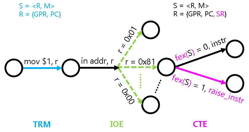
The program is a state machine S = <R, M>, and we have previously discussed the specific behavior of this state machine in TRM and IOE. If we want to add an exception response mechanism to the computer, how should we expand this state machine?
First of all, it is necessary to expand R, in addition to the Program Counter (PC) and the General-Purpose Registers, we also need to add some special registers mentioned earlier. We might as well call these registers System Registers (SR), because their functions are related to system features and are not used during regular computation. After the expansion, the registers can be represented as R = {GPR, PC, SR}. The exception response mechanism is unrelated to memory, so there is no need to modify the meaning of M.
The expansion of state transitions is quite interesting. Previously, we assumed that every instruction executed by the program would succeed, thus the state machine would transition states based on the semantics of the instruction. After adding an exception response mechanism, we allow for the possibility that the execution of an instruction can "fail." To describe the behavior of a failed instruction execution, we can assume that the CPU has a hypothetical instruction raise_intr, whose execution represents the exception response process mentioned earlier. Clearly, this behavior can be described from the perspective of a state machine. For example, in riscv32, it can be represented as:
SR[mepc] <- PC
SR[mcause] <- A number describing the reason for the failure
PC <- SR[mtvec]
With this hypothetical instruction, we can now understand the behavior of exception handling from the perspective of a state machine: If an instruction executes successfully, its behavior is the same as the previously introduced TRM and IOE; If an instruction fails to execute, its behavior is equivalent to executing the hypothetical raise_intr instruction.
So, is the "failure of an instruction execution" a deterministic event? Obviously, this depends on the definition of "failure." For example, division by zero is defined as "the second operand of the division instruction is zero," an illegal instruction can be defined as "an instruction that does not fall within the description of the ISA manual," and a trap instruction can be considered a special case of unconditional failure. Different ISA manuals have their own definitions of "failure." For instance, the RISC-V manual does not consider division by zero as a failure. Therefore, even if the divisor is zero, the instruction will still be executed according to the instruction manual in a RISC-V processor.
In fact, we can represent these failure conditions as a function fex: S -> {0, 1}. Given any state S of the state machine, fex(S) can uniquely determine whether the instruction pointed to by the current PC can be executed successfully. Therefore, adding an exception response mechanism to the computer does not increase the system's non-determinism. This greatly reduces the difficulty of understanding the exception response mechanism and makes debugging less challenging: When a program is run multiple times, it will still throw the same exception at the same location, resulting in the same state transition (The input instructions of IOE introduce some non-determinism, but it is still within our control for now).
Finally, the addition of an exception response mechanism is accompanied by the inclusion of some system instructions, such as x86's lidt, iret, and riscv32's csrrw, mret, etc. Apart from being used specifically to operate on the SR in the state machine, these instructions are not fundamentally different from the computational instructions in TRM. Therefore, their behavior is not difficult to understand.
Abstracting Context Management as CTE
We just mentioned the state of a program, and there is an equivalent term in the operating system called "context." Therefore, the aforementioned hardware-provided functionality for switching the execution flow between the operating system and user programs can be considered as part of context management from the operating system's perspective.
Similar to IOE, the specific implementation of context management is also architecture-dependent: For example, as mentioned earlier, x86/mips32/riscv32 use int/syscall/ecall instructions respectively to perform traps, and in native, some magical library functions can even be used to simulate the corresponding functionality; Moreover, the specific contents of the context are obviously different across architectures (for instance, the registers are already different). Therefore, we can categorize the functionality of context management into a new class of APIs in AM, called CTE (ConText Extension).
The next question is, how do we abstract the context management functionality of different architectures into a unified API? In other words, we need to consider what information the operating system's handling process actually requires.
- First, of course, is the reason that triggered this execution flow switch. Was it a division by zero, an illegal instruction, a breakpoint trigger, or did the program voluntarily trap into the operating system? Based on different reasons, the operating system will perform different handling.
- Next is the program's context. During the handling process, the operating system may read some registers from the context and use their information for further processing. For example, the operating system reads the illegal instruction pointed to by the PC and checks if it can be simulated. In fact, through this context, the operating system can even implement some magical features. You will learn more details about this in PA4.
Simulating Instructions with Software
In some embedded scenarios, processors have very strict requirements for low power consumption, and the Floating-Point Unit (FPU) is often removed to save power. In this case, if the software tries to execute a floating-point instruction, the processor will throw an illegal instruction exception. With the exception response mechanism, we can simulate the execution of this illegal instruction during the exception handling process, which is very similar to the instruction execution process in PA2. In various processors without an FPU, floating-point instructions can be executed through this method.
Executing Floating-Point Instructions in AM is UB
In other words, the runtime environment of AM does not support floating-point numbers. This sounds too aggressive. The reason for this decision is that IEEE 754 is an industry-standard, and to ensure the soundness and completeness of the formalized logic, the standard may have various strange settings, such as different rounding modes, the introduction of inf and nan, etc. For teaching purposes, it is not necessary to understand all their details; but if you want to implement a correct FPU, you cannot escape these details.
Unlike the fixed-point instructions in PA2, floating-point instructions are used less frequently in PA, and we have other ways to work around them. So, we chose the simplest approach, which is to make it UB. Of course, if you are interested, you can also consider implementing a simplified version of an FPU. After all, it is UB, so if your FPU behaves correctly, it does not violate the rules.
Another UB
Another UB you might encounter is stack overflow, yes, the stackoverflow. Detecting stack overflow requires a more powerful runtime environment, which AM is definitely incapable of handling, so it is UB.
However, how much stack space does AM actually provide for programs? In fact, if you tried to understand every detail during PA2, you already know the answer to this question; if you didn't, you need to reflect on yourself and carefully RTFSC (Read The F Source Code).
So, as long as we abstract these two pieces of information into a unified representation, we can define the API for CTE. For the reason for the switch, we only need to define a unified way to describe it. CTE defines the following data structure called "event" (see abstract-machine/am/include/am.h)
typedef struct Event {
  enum { ... } event;
  uintptr_t cause, ref;
  const char *msg;
} Event;
Among them, event represents the event number, cause and ref are some supplementary information describing the event, and msg is the event information string. In PA, we will only use event. Then, we only need to define some unified event numbers (the enumeration constants above), and let each architecture describe the reason for the context switch through the above structure when implementing their respective CTE APIs, thus achieving the abstraction of the switch reason.
For the context, we can only unify the name of the structure type that describes the context to Context. As for the specific contents within it, further abstraction is not possible. This is mainly because the differences in context information between different architectures are too large. For example, mips32 has 32 general-purpose registers. From this point alone, it is destined that the Context of mips32 and x86 cannot be abstracted into a completely unified structure. Therefore, in AM, the specific members of Context are defined by different architectures themselves. For instance, the Context structure of x86-nemu is defined in abstract-machine/am/include/arch/x86-nemu.h. Consequently, direct references to Context members in the operating system are architecture-dependent behaviors that can compromise the portability of the operating system. However, in most cases, the operating system does not need to access the members of the Context structure individually. CTE also provides some interfaces to allow the operating system to access them when necessary, ensuring that the relevant code of the operating system is architecture-independent.
Finally, there are two other unified APIs:
bool cte_init(Context* (*handler)(Event ev, Context *ctx))is used to perform CTE-related initialization operations. It also accepts a pointer to an event handling callback function from the operating system. When an event occurs, CTE will call this callback function with the event and the associated context as arguments, handing it over to the operating system for subsequent processing.void yield()is used to perform a trap operation, which triggers an event with the numberEVENT_YIELD. Different ISAs will use different trap instructions to trigger the trap operation. For specific implementations, please RTFSC (Read The F Source Code).
There are other APIs in CTE that are not currently used, so they will not be introduced for now.
Next, let's try to trigger a trap operation through the yield test in am-tests to sort out the details in the process. This test also supports timer interrupts and external interrupts, but they require hardware support for interrupt-related functionality, which we don't care about for now.
Update am-kernels
We updated the code for yield test on October 3, 2023, at 15:35:00. If you obtained the code for am-kernels before this time, please use the following command to get the updated code:
cd am-kernels
git pull origin master
Setting the Exception Entry Address
Before triggering a trap operation, it is necessary to set the exception entry address according to the ISA's convention, so that the execution flow can jump to the correct exception entry when switching in the future. This is obviously an architecture-dependent behavior, so we put this behavior into CTE instead of letting am-tests directly set the exception entry address. When we select yield test, am-tests will initialize CTE through the cte_init() function, which includes some simple macro expansion code. This will eventually call the cte_init() function located in abstract-machine/am/src/$ISA/nemu/cte.c. The cte_init() function does two things, the first of which is to set the exception entry address:
- For x86, it is necessary to prepare a meaningful IDT
- The code defines a structure array
idt, where each element is a gate descriptor structure - Fill in meaningful gate descriptors in the corresponding array elements. For example, the gate descriptor with number
0x81contains the entry address for the trap operation. It should be noted that the framework code still fills in the complete gate descriptor (including the don't care fields mentioned above), mainly to allow KVM to jump to the correct entry address during DiffTest. KVM implements a complete x86 exception response mechanism, and if only a simplified version of the gate descriptor is filled in, the code will not run correctly in it. But we don't need to understand the details; we only need to know that the code has filled in the correct gate descriptors. - Use the
lidtinstruction to set the base address and length ofidtin IDTR
- The code defines a structure array
- For mips32, since the exception entry address is fixed at
0x80000180, we need to place an unconditional jump instruction at0x80000180, making the jump target of this instruction the real exception entry address we want. - For riscv32, directly set the exception entry address to the mtvec register
The second thing the cte_init() function does is to register an event handling callback function, which is provided by yield test. More information will be introduced later.
Triggering a Trap Operation
After returning from the cte_init() function, yield test will call the test main function hello_intr(), which first outputs some information and then starts the input device through io_read(AM_INPUT_CONFIG). However, in NEMU, this startup does not have any actual operation. Next, hello_intr() will enable interrupts through iset(1), but since we haven't implemented interrupt-related functionality yet, we can also ignore this part of the code. Finally, hello_intr() will enter the test main loop: the code will keep calling yield() to perform trap operations. To prevent the calling frequency from being too high and causing the output to be too fast, an empty loop is added to the test main loop for idle spinning.
To support trap operations and test whether the exception entry address has been set correctly, you need to implement the isa_raise_intr() function in NEMU (defined in nemu/src/isa/$ISA/system/intr.c) to simulate the exception response mechanism mentioned above.
It should be noted that:
- PA does not involve privilege level switching, so you don't need to pay attention to the content related to privilege level switching when RTFM (Reading The F Manual).
- You need to call
isa_raise_intr()in the implementation of the trap instruction, rather than implementing the exception response mechanism code in the helper function of the trap instruction, because we will use theisa_raise_intr()function again later. - If you choose x86, when indexing the IDT using the address in IDTR, you need to use
vaddr_read()
Implement the Exception Response Mechanism
You need to implement the new instructions mentioned above and implement the isa_raise_intr() function. Then read the code of cte_init() and find the corresponding exception entry address.
If you choose mips32 and riscv32, you will find that there are many status bits in the status/mstatus register. However, not implementing the functionality of these status bits at present does not affect the execution of the program. Therefore, for now, you only need to consider the status/mstatus register as a register used to store 32-bit data.
After implementation, rerun yield test. If you find that NEMU indeed jumps to the exception entry address you found, it means your implementation is correct (NEMU may also terminate due to triggering an unimplemented instruction).
Enable DiffTest to Support the Exception Response Mechanism
To make the DiffTest mechanism work correctly, you need to
- For x86:
- NEMU does not implement the segmentation mechanism and does not have the concept of the cs register. However, to smoothly perform DiffTest, you still need to add a cs register to the cpu structure and initialize it to
8. - Since x86's exception response mechanism requires pushing eflags onto the stack, you also need to initialize eflags to
0x2.
- NEMU does not implement the segmentation mechanism and does not have the concept of the cs register. However, to smoothly perform DiffTest, you still need to add a cs register to the cpu structure and initialize it to
- For riscv32, you need to initialize
mstatusto0x1800. - For riscv64, you need to initialize
mstatusto0xa00001800.
Saving the Context
After successfully jumping to the exception entry address, we need to start the real exception handling process in software. However, when performing exception handling, it is inevitable to use general-purpose registers, but looking at the current general-purpose registers, they contain the contents before the context switch. These contents are also part of the context. If they are overwritten without saving them, it will be impossible to restore this context in the future. But usually, the hardware is not responsible for saving them, so their values need to be saved through software code. x86 provides the pusha instruction to push the values of general-purpose registers onto the stack; while mips32 and riscv32 push each general-purpose register onto the stack in turn using the sw instruction.
In addition to the general-purpose registers, the context also includes:
- The PC and processor status when the exception is triggered. For x86, they are eflags, cs, and eip, and x86's exception response mechanism has already saved them on the stack; for mips32 and riscv32, they are the epc/mepc and status/mstatus registers. The exception response mechanism saves them in the corresponding system registers, and we still need to read them from the system registers and save them on the stack.
- Exception number. For x86, the exception number is saved by software; while for mips32 and riscv32, the exception number has already been saved by hardware in the cause/mcause register, and we still need to save it on the stack.
- Address space. This is prepared for PA4. In x86, it corresponds to the
CR3register, and the code reserves space on the stack through apushl $0instruction. In mips32 and riscv32, the address space information shares storage space with register 0. Anyway, the value of register 0 is always 0, so there is no need to save and restore it. However, we are not currently using address space information, so you can ignore their meaning for now.
Saving the Exception Number
x86 saves the exception number through software and does not have a register similar to cause. Can mips32 and riscv32 do the same? Why?
Thus, these contents constitute the complete context information. The exception handling process can diagnose and handle the exception based on the context, and this information is also needed when restoring the context in the future.
Comparing Exception Handling and Function Calls
We know that when making a function call, it is also necessary to save the caller's state: the return address and the registers that need to be saved by the caller according to the calling convention. However, CTE saves more information when saving the context. Try to compare them and think about what causes the difference in the information they save.
Next, the code will call the C function __am_irq_handle() (defined in abstract-machine/am/src/$ISA/nemu/cte.c) to handle the exception.
Bizarre x86 Code
In x86's trap.S, there is a line of code pushl %esp, which at first glance seems quite bizarre. Can you understand its behavior in the context of the surrounding code? Hint: The program is a state machine
Reorganize the Context Structure
Your tasks are as follows:
- Implement the new instructions needed in this process. For details, please RTFM.
- Understand the process of context formation and RTFSC, then reorganize the members of the
Contextstructure defined inabstract-machine/am/include/arch/$ISA-nemu.h, so that the order of these members is consistent with the context constructed inabstract-machine/am/src/$ISA/nemu/trap.S.
It should be noted that although we are not currently using the address space information mentioned above, you still need to handle the position of the address space information correctly when reorganizing the Context structure, otherwise, you may encounter difficult-to-understand errors in PA4.
After implementation, you can output the contents of the context c in __am_irq_handle() using printf, and then observe the register state when the trap is triggered using the simple debugger to check if your Context implementation is correct.
Let me give you some hints
There's not much to say about "implementing new instructions." You have already implemented many instructions in PA2. "Reorganizing the structure" is a very interesting topic. If you don't know what to do, you might as well start by understanding the question. The general idea of the question is to define a structure in $ISA-nemu.h based on the contents of trap.S. trap.S is obviously assembly code, while $ISA-nemu.h contains a structure defined in C language. Assembly code and C language... Wait, you seem to recall some content from the ICS textbook.
I made some random changes and it passed, hehehe
If you still have this lucky mentality, you will have a very painful experience in PA3. In fact, "understanding how to correctly reorganize the structure" is a very important part of PA3. So let's add a required question.
Required Question (needs to be answered in the lab report) - Understanding the past and present of the context structure
You will see a context structure pointer c in __am_irq_handle(). Where exactly is the context structure pointed to by c? And how did this context structure come about? Specifically, the context structure has many members. Where is each member assigned a value? What is the relationship between the four parts: $ISA-nemu.h, trap.S, the above lecture text, and the new instructions you just implemented in NEMU?
If you are not smart enough, it's better not to stare at the code with your eyes wide open. To understand the details of the program, you should still start from the state machine perspective.
Event Distribution
The code in __am_irq_handle() packages the reason for the execution flow switch into an event, and then calls the event handling callback function registered in cte_init(), passing the event to yield test for handling. In yield test, this callback function is the simple_trap() function in am-kernels/tests/am-tests/src/tests/intr.c. The simple_trap() function further dispatches based on the event type. However, we will trigger an unhandled event here:
AM Panic: Unhandled event @ am-kernels/tests/am-tests/src/tests/intr.c:12
This is because the __am_irq_handle() function in CTE did not correctly identify the trap event. According to the definition of yield(), the __am_irq_handle() function needs to package the trap event into an event with the number EVENT_YIELD.
Identify the Trap Event
You need to identify the trap exception in __am_irq_handle() based on the exception number and package it into a trap event with the number EVENT_YIELD. Rerun yield test. If your implementation is correct, you will see the character y output after identifying the trap event.
Restore Context
The code will return all the way back to __am_asm_trap() in trap.S, and the next step is to restore the program's context. __am_asm_trap() will restore the program's state based on the previously saved context information, and finally execute the "exception return instruction" to return to the state before the program triggered the exception.
However, it should be noted that the PC saved by the previous trap instruction. For the x86 int instruction, the saved PC points to the next instruction, which is a bit like a function call; while for mips32's syscall and riscv32's ecall, the saved PC is the PC of the trap instruction itself, so the software needs to add 4 to the saved PC at an appropriate place to return to the next instruction after the trap instruction in the future.
Looking at the Add 4 Operation from the Perspective of CISC and RISC
In fact, traps are just one type of exception. There is a type of fault exception where the returned PC is the same as the PC that triggered the exception, such as a page fault. After the system resolves the fault, it will re-execute the same instruction for a retry, so the PC returned by the exception does not need to add 4. Therefore, depending on the type of exception, sometimes it is necessary to add 4, and sometimes it is not.
At this point, we can consider the following question: Who decides whether to add 4 or not, the hardware or the software? CISC and RISC have opposite approaches. CISC leaves it to the hardware, while RISC leaves it to the software. Think about it, what are the trade-offs between these two approaches? Which one do you think is more reasonable? Why?
The code will finally return to the location in yield test where the trap was triggered and continue execution. From its perspective, it's as if this journey through time and space never happened.
Restore the Context
You need to implement the new instructions in this process. Rerun yield test. If your implementation is correct, yield test will continuously output y.
Required Question (needs to be answered in the lab report) - Understanding the Journey Through Time and Space
From the moment yield test calls yield() to the moment it returns from yield(), what exactly does this journey entail? How do the software (AM, yield test) and hardware (NEMU) work together to complete this journey? You need to explain every detail in this process, including the behavior of each line of assembly code/C code involved, especially some of the more critical instructions/variables. In fact, the previous required question "Understanding the past and present of the context structure" has already covered a part of this journey, and you can include its answer here.
Don't be intimidated by "every line of code." This process only involves about 50 lines of code, and it's not impossible to fully understand it thoroughly. The reason we set up this required question is to force you to clearly understand every detail in this process. This understanding is so important that if you lack it, you will be almost helpless when facing bugs in the future.
MIPS32 Delay Slots and Exceptions
We mentioned in PA2 that standard MIPS32 processors use branch delay slot technology. Think about it, if a standard MIPS32 processor triggers an exception while executing a delay slot instruction, what problems might occur after returning from the exception? How should it be resolved? Try RTFM to compare your solution.
Traces of Exception Handling - etrace
Exceptions thrown by the processor can also reflect the behavior of program execution, so we can also record the traces of exception handling (exception trace). You may think that outputting information through printf() in CTE can achieve a similar effect, but this approach still has the following differences compared to the etrace implemented in NEMU:
- Enabling etrace does not change the behavior of the program (it is non-intrusive to the program): You may encounter some bugs in the future, and when you try to insert some
printf()statements, the behavior of the bug will change. For such bugs, etrace can still help you diagnose them because it outputs in NEMU and does not change the behavior of the program. - etrace is also not affected by program behavior: If the program contains some fatal bugs that prevent it from entering the exception handling function, then it is not possible to call
printf()in CTE to output; in this case, etrace can still work normally.
In fact, QEMU and Spike have also implemented functionality similar to etrace. If the system software running on them encounters errors, developers can also use these features to quickly locate and diagnose bugs.
Implement etrace
You have already implemented many trace tools in NEMU, so implementing etrace naturally won't be a problem for you.
Friendly Reminder
Stage 1 of PA3 ends here.