F4 State Machine Model of Computer Systems
Before we further study how to design processors, let's first understand the basic principles of how processors work. However, we will not introduce processors from the perspective of digital circuits for the time being.Instead, we will explain some important concepts related to processors through a less rigorous mathematical model. Therefore, you can temporarily set aside the digital circuit knowledge you learned in the previous section.Processors and digital circuits are indeed closely related. In the next section, we will discuss how to implement processors using digital circuits.For now, all you need is paper and a pen.
The Composition and Working Principle of Processors
A computer is a device that mechanically processes data. Here, 'mechanically' refers to the fact that its principles are straightforward and easy to understand. The central processing unit (CPU), which acts as the brain of the computer, is also such a device.
Instructions and Their Codes
You should all be familiar with electronic calculators. Modern calculators can perform at least the four arithmetic operations of addition, subtraction, multiplication, and division. The functionality of a processor far exceeds that of an electronic calculator. As a device for processing data, its processing methods are certainly not limited to a single approach. Additionally, since a processor is a device that mechanically processes data, the type of processing it performs should be controlled by some means, and it does not possess the ability to think independently. The medium for controlling the processor is instructions. For example, we can use an addition instruction to control the processor to add two pieces of data together.This is very similar to entering 1+2= on an electronic calculator to control it.
To 'use an addition instruction to control the processor to add two pieces of data', it means that an instruction needs to provide two types of information: On one hand, there are many types of data that a computer needs to process, so the instruction must specify which data to process, which is referred to as the 'operand' field of the instruction; On the other hand, there are also many ways for a computer to process data, so the instruction must also specify the method of data processing, which is referred to as the 'opcode' field of the instruction.
+--------+---------------+
| opcode |    operand    |
+--------+---------------+
It has been noted that some intermediate results of data processing should be saved for subsequent use. Therefore, the processor should have components capable of storing processed data, which are known as registers. For the convenience of storing data, there is usually more than one such register, but rather a group of registers called a 'Register Set' ( some textbooks also refer to it as a 'Register File'). Since such a register set is used for processing general data, these registers are also referred to as general purpose registers (GPR). In contrast, some registers are not designed for general-purpose processing and do not belong to the GPR category.
For example, to calculate 1+2+...+10, but a single addition instruction can only calculate the sum of two data items, so the result of 1+2 needs to be stored in a register r in the GPR, and then r+3 is calculated, and so on. In this way, the instruction needs to specify in the operand field which GPR to read the data from and which GPR to store the calculation result in. As for the opcode, the processor only needs to agree on what each opcode represents.
As a digital circuit, the processor can represent all information using 0 and 1, and instructions are no exception. For example, a simple processor with 4 GPRs supports 3 types of instructions, two of which are as follows:
 7  6 5  4 3   2 1   0
+----+----+-----+-----+
| 00 | rd | rs1 | rs2 | R[rd]=R[rs1]+R[rs2]    add instruction, add two registers together
+----+----+-----+-----+
| 10 | rd |    imm    | R[rd]=imm              li instruction, load immediate value, fill high bits with zeros
+----+----+-----+-----+
Since there are only three types of instructions, a minimum of two opcodes can be used to distinguish between all instructions. In the above example, the opcode is 00, which represents the add instruction; the opcode is 10, which represents the li instruction. For convenience, instructions usually have corresponding names, such as the add instruction and the li instruction.
Regarding operands, since there are only 4 GPRs, a 2-bit number can be used to specify the address of a GPR (00, 01, 10, 11). The source of the operand data is called the 'source register.' The above add instruction requires two source registers to obtain the addends, with the addresses of the two source registers denoted as rs1 and rs2, respectively, and the contents stored in the GPRs represented as R[rs1] and R[rs2]; The destination where the operation is written is called the 'destination register', generally denoted as rd. Among these, the second li instruction has a slightly different operand format. Its source operand is no longer a GPR, but is directly parsed from the imm field in the instruction into a binary number for use. This type of operand is called an 'immediate operand'.
In summary, the length of the above instructions is 8 bits. We can understand the meaning of an instruction based on the above instruction encoding rules. Some specific instruction examples are as follows:
00100001   add instruction, add R[0] and R[1], and write the result to R[2]
10110000   li instruction, write the immediate value 0000 to R[3]
10000101   li instruction, write the immediate value 0101 to R[0]
Stored-Program
In fact, computers, which we believe to be almost omnipotent, complete various complex tasks by continuously executing a series of instructions. The various software programs you run on your computer are ultimately executing a series of instructions. Therefore, the essence of a program is a sequence of instructions. You may find it hard to believe, because the above instructions are very simple and no different from those of an electronic calculator. So why are computers so much more powerful than electronic calculators?
The answer lies in how computers work: they allow programs to automatically control the computer's execution. Specifically, we can first store a sequence of instructions in memory (such as the RAM of modern computers), and have the computer fetch instructions from memory to execute; crucially, after the computer completes executing one instruction, it proceeds to execute the next instruction. To enable the computer to know where the next instruction is located, there must also be a component that indicates which instruction is currently being executed, this component is called the 'Program Counter' (PC).
From now on, computers only need to do one thing:
Repeat the following steps:
  Fetch the instruction from the memory location indicated by the PC.
  Execute the instruction.
  Update the PC.
In this way, we only need to place a sequence of instructions in the memory, then let the PC point to the first instruction, and the computer will automatically execute this sequence of instructions without stopping. This is the basic idea of 'Stored-Program' computers. Today's mainstream computers are essentially all 'Stored-Program' computers.
There is an even more ingenious design! Since the PC stores the location of the currently executing instruction, the PC should also be a register. In this case, we can also design corresponding instructions to modify it, thereby increasing the flexibility of the program execution process. For example, we can add a third instruction based on the two instructions mentioned above:
 7  6 5         2 1  0
+----+---- -----+-----+
| 11 |   addr   | rs2 | if (R[0]!=R[rs2]) PC=addr bner0 instruction, if not equal to R[0], jump
+----+----------+-----+
The bner0 instruction is quite special; it stands for Branch if Not Equal r0. If R[rs2] and R[0] are not equal when this instruction is executed, the PC register is updated to addr, meaning that the PC points to the instruction at addr. However, the PC register is not used to process general data, so it does not belong to the GPR.
With these instructions, we can now have the computer perform some more complex tasks.
An Example of Summing a Sequence of Numbers
Let's use instructions to calculate the sum of the sequence 1+2+...+10. For ease of understanding, we will not use 0 and 1 to represent instructions. We will use r0, r1, r2, and r3 to represent the four GPRs, and use commas to separate the operands of the instructions. Assume the following instruction sequence is stored in memory to calculate the sum of the above sequence, where the number before : represents the program counter (PC), and the text following # represents a comment:
0: li r0, 10   # This is decimal 10.
1: li r1, 0
2: li r2, 0
3: li r3, 1
4: add r1, r1, r3
5: add r2, r2, r1
6: bner0 r1, 4
7: bner0 r3, 7
At first glance, you may find it difficult to understand how the above instruction sequence implements the summation of a sequence. Let's imagine ourselves as a processor and understand the process by executing each instruction one by one. To understand the process of instruction execution, we also need to record the changes in the registers. We use the format (PC, r0, r1, r2, r3) to record the values of the registers, which also reflects the state of the processor. For example, (7, 2, 3, 1, 8) indicates that the next instruction to be executed is numbered 7, and the current values of the four GPRs are 2, 3, 1, and 8. We agree that at the start, the processor's state is (0, 0, 0, 0, 0). The following is the process of the processor executing several instructions:
PC r0 r1 r2 r3
(0, 0, 0, 0, 0)   # initial state
(1, 10, 0, 0, 0)  # After executing the instruction with PC = 0, r0 is updated to 10, and PC is updated to the location of the next instruction.
(2, 10, 0, 0, 0)  # After executing the instruction with PC = 1, r1 is updated to 0, and PC is updated to the location of the next instruction.
(3, 10, 0, 0, 0)  # After executing the instruction with PC = 2, r2 is updated to 0, and PC is updated to the location of the next instruction.
(4, 10, 0, 0, 1)  # After executing the instruction with PC = 3, r3 is updated to 1, and PC is updated to the location of the next instruction.
(5, 10, 1, 0, 1)  # After executing the instruction with PC = 4, r1 is updated to r1 + r3, and PC is updated to the location of the next instruction.
(6, 10, 1, 1, 1)  # After executing the instruction with PC = 5, r2 is updated to r2 + r1, and PC is updated to the location of the next instruction.
(4, 10, 1, 1, 1)  # After executing the instruction with PC = 6, since r1 does not equal r0, PC is updated to 4.
(5, 10, 2, 1, 1)  # After executing the instruction with PC = 4, r1 is updated to r1 + r3, and PC is updated to the location of the next instruction.
......
Continue to implement the above instructions.
Try to continue executing the instructions and record the changes in the register states. What state is the processor in when the execution is complete? In which register is the sum of the above sequence stored?
As you can see, the processor works by mechanically updating the status of the registers according to the meaning of the instructions. At this point, you have understood the basic principles of how a processor works.
In fact, the advantage of computers lies in their extremely fast processing speed: the clock speed of modern processors has reached the GHz level. Taking 2GHz as an example, this means that the processor undergoes 2,000,000,000 clock cycles in one second. Using the aforementioned instruction sequence to calculate 1+2+...+10 requires fewer than 40 instructions. If we assume one instruction is executed per cycle, a modern processor would only need 0.00000002 s, or 20 ns, to complete the calculation. If we were to manually use an electronic calculator, pressing 10 keys per second would already be considered very fast,but entering 1+2+...+10= would require 22 key presses, which would take approximately 2 seconds. To calculate 1+2+...+10000, we simply need to modify the above instruction with a PC of 0 to li r0, 10000. (though a longer instruction is needed to represent the immediate value 10000), and using the same method, it would take approximately 30,000 instructions, which would only take 0.000015 s, or 15 us. If done manually on an electronic calculator, it would require pressing the keys 48,894 times, which would take 4,889 seconds! Even if we use the formula for the sum of an arithmetic sequence ((10,000 + 1) * 10,000 / 2) to calculate mentally, it would still take several seconds to arrive at the correct answer, which pales in comparison to the power of a computer.
Rethinking Programming
You may have been exposed to programming languages before, but you probably haven't thought much about the essence of programming. Programming is actually the process of completing complex tasks by combining given functions. You may have been exposed to programming languages such as C++, Python, and Scratch, which are all high-level programming languages. The example above, which uses a combination of instructions to calculate the sum of a sequence, is also programming!
The above instructions, such as add and li, belong to the category of assembly language in the field of computer science. Assembly language is a symbolic representation of instructions. Compared with assembly language, there is an even lower-level machine language, which is the binary representation of instructions. It can be directly executed by a processor implemented through digital circuits. For example, the machine language representation of the above sequence summation program is as follows:
10001010    # 0: li r0, 10
10010000    # 1: li r1, 0
10100000    # 2: li r2, 0
10110001    # 3: li r3, 1
00010111    # 4: add r1, r1, r3
00101001    # 5: add r2, r2, r1
11010001    # 6: bner0 r1, 4
11011111    # 7: bner0 r3, 7
In fact, the above machine language representation translates assembly language into a sequence of 0s and 1s based on the instruction encoding agreed upon earlier. As long as you understand the encoding rules for instructions, assembly language and machine language can be converted back and forth. However, it is difficult for programmers to understand machine language on its own. In contrast, assembly language can represent instruction opcodes and operands more intuitively, making it more readable than machine language.
Calculate the Sum of Odd Numbers Less than 10.
Try writing a program using the above instructions to calculate the sum of odd numbers less than 10, i.e., calculate 1+3+5+7+9. After writing the program, try to list the changes in the processor status to check whether the program you wrote is correct.
State Machine Model of Instruction Set Architecture
The aforementioned GPR, PC, memory, instructions, and their execution processes belong to the category of Instruction Set Architecture (ISA) in the field of computer science. You may have heard of concepts such as x86, ARM, and RISC-V; these are all examples of ISAs. The example mentioned earlier with only three instructions is also a type of ISA. For convenience, we refer to it as sISA (simple ISA).
The essence of ISA is a set of specifications, which are typically documented in corresponding manuals. These specifications define the functions and behaviour of a model machine. A model machine is a machine that exists only in the mind. We discuss only its functions and behaviour, not its specific implementation. Therefore by studying the model machine, we can separate principles from implementation details, which helps us understand the essence of a processor. When we implement this model machine in our minds through digital circuits, we obtain a real computer.
Before further explaining what ISA specifically includes, let's first introduce a mathematical model that is very important for our understanding of computer systems: the state machine.
The definition of a state machine includes the following parts:
- State set
- Event set
- State transition rules
- Describe the next state of each state under different events, i.e., the binary function specifies the next state after receiving stimulus event while in state
- Initial state
Although the above definition is not 100% rigorous in a mathematical sense, it is sufficient for us to understand the behaviour of computer systems.
Now let's understand ISA from the perspective of a state machine:
- State set. Recall the relevant content of sequential logic circuits: states are elements that can stably store information. Extending this meaning, in ISA, states should include PC, GPR, and memory. That is, a state in the ISA is a specific combination of PC, GPR, and memory, and the set of all states is the combination of all possible values of PC, GPR, and memory, i.e., .
- Set of events. In the ISA, executing an instruction changes the state, so executing an instruction is the event for this state machine.
- State transition rules. By definition, in the ISA, state transition rules describe the 'next state after executing a certain instruction in a given state,' i.e., the semantics of the instruction. They specify how the state should change after executing a certain instruction, thereby transitioning from one state to another.
- Initial state. The state before any instructions have been executed.
Taking the aforementioned sISA as an example, its state machine model is as follows:
- State set . For example, in the sequence summation example, a certain statewhere denotes the information stored in memory, which is the encoding of the instruction sequence mentioned earlier. However, since instructions in sISA do not modify the information stored in memory, to simplify the representation, we can omit the description of memory in the state: .
- As a specific ISA, sISA also uses instruction execution as the event.
- In sISA, the state transition rules are the semantics of the following three instructions:For example, means that when the state is , executing the instruction
7 6 5 4 3 2 1 0 +----+----+-----+-----+ | 00 | rd | rs1 | rs2 | R[rd]=R[rs1]+R[rs2] add instruction, add two registers together +----+----+-----+-----+ | 10 | rd | imm | R[rd]=imm li instruction, load immediate number, fill high bits with zeros +----+----+-----+-----+ | 11 | addr | rs2 | if (R[0]!=R[rs2]) PC=addr bner0 instruction, if not equal to R[0], then jump +----+----------+-----+00101001results in the next state . According to the above, the behaviour of this instruction isR[2] = R[2] + R[1], so . This is actually one of the steps in the execution process of the above sequence summation example. - Initial state .
Life Is Like a Play.
We have already explained how computers work using natural language and examples of summing sequences in the preceding text. The reason we are introducing the state machine model filled with mathematical symbols is to help you uncover the mystery of computers: Since their birth, the working process of computers has been a mathematical game, and the state machine model is simply the rules of this mathematical game.
In fact, whether it is the instruction set mentioned above or the programs and processors we will introduce later, these core concepts of computers are fundamentally consistent: they are all part of the mathematical game known as the state machine. Therefore, if you have mastered the rules of the game mentioned above, you are already prepared to understand computers.
As for commercial-grade real ISAs such as x86, ARM, and RISC-V, they have more GPRs, more instructions, and more complex instruction behaviour. However, their fundamental principles are essentially the same as those of the sISA with only three instructions mentioned above. Therefore, if you need to understand them in the future, you only need to read the corresponding manuals to learn more about the details of the instructions.
C Programming for Beginners
The above section introduced assembly language. Although assembly language can be used for programming, it is inconvenient for developing larger programs. This is because programming in assembly language requires attention to how data flows between GPRs, and each instruction can generally perform only a few operations. Even a simple program logic may require dozens of instructions to express. In fact, modern program development typically uses advanced programming languages.
There are many advanced programming languages, but we chose C because it is one of the simpler ones among high-level programming languages. We can easily associate C with the working process of computer systems, which helps us understand the essence of computers.
A Simple C Language Example
Let's start with a simple code example:
/* 1 */ int main() {
/* 2 */   int x = 1;
/* 3 */   int y = 2;
/* 4 */   int z = x + y;
/* 5 */   printf("z = %d\n", z);
/* 6 */   return 0;
/* 7 */ }
This example calculates 1+2 and outputs the result. Let's explain the details of the code:
- The content between
/*and*/is a comment in C language. Comments do not affect the logic of the program, so they are mainly for programmers to read. For example, the above code and the following code are logically equivalent:/* This is an example. */ int main() { int x = 1; int y = 2; int z = x + y; printf("z = %d\n", z); return 0; } intrepresents the integer type, which is short forinteger.
int main() { ... }defines a function namedmain. Functions are the basic modules of the C language. The process of executing a C program is the process of executing the function code in the C program. In particular, themainfunction is a special function. It is the entry point of the C program, which means that the C program will start executing from themainfunction.
- The content within curly brackets
{ ... }is the function body, which consists of statements. Each statement is used to instruct the program to perform an operation. The statements within curly brackets are executed in order by default.
int x = 1;defines a variable namedxand assigns it an initial value of1. Variables are objects that store information in a program, similar to the GPR mentioned above. In C language, a statement ends with a semicolon;.int y = 2;works the same way.int z = x + y;defines a variablezand assigns it an initial value ofx + y.
printf(‘z = %d\n’, z);is a function call statement that calls the functionprintf. Function calls in programs are similar to calculating function values in mathematics. For example, in mathematics, given that , the process of finding involves substituting into the definition of and performing the calculation;printf(‘z = %d\n’, z);substitutes the two parameters‘z = %d\n’andzinto the definition ofprintfand executes it. In a C program,printfis a special function used to output information to the terminal. The%din the first parameter indicates that the second parameterzshould be output in decimal format. Therefore, the above function call outputs the current value of the variablezin decimal format to the terminal.
return 0;is a function return statement, indicating that the function has finished executing, and returning0as the calculation result to the statement that called the function.
Run C Programs Online
You can run the above C program on the online website Compiler Explorer. Specifically, after entering the above C code in the code editor, click Add new... in the toolbar above the editor, select Execution Only, and a terminal window with the execution results will pop up. If you have done everything correctly, you will see z = 3 output in the terminal window.
You can try modifying the C code according to your understanding and observe the program's output.
Hint: You can bookmark this website, as you will use it as a development environment in the early stages of Phase E.
It should be noted that the above explanation does not cover all the relevant details of the C language. Some details cannot be explained clearly at this time, so we will omit them for now. However, the above explanation is sufficient to help you understand the rest of the lecture notes.
State Machine Model of C Programs
Perhaps you have already sensed that the concepts of variables and statements in C language are somewhat similar to the concepts of GPR and instructions mentioned above in ISA. In fact, from the perspective of computer systems, they are indeed closely related. Similar to ISA, we can also understand C programs from the perspective of state machines:
- State set. In C programs, the most direct state is variables, as they are objects that store information. In addition, as mentioned earlier:
the statements within curly braces are executed in order by default. Naturally, during the execution of a C program, there also needs to be an implicit variable to indicate which statement is currently being executed, this implicit variable is the 'program counter' (PC) in the C language, and it should also be part of the state. Therefore, in a C program, a state is a set of specific variables and the PC, and the set of all states is the combination of all possible values of variables and the PC, i.e., , where represents the values of all variables in the program. - Set of events. In C programs, execution statements change the state, so execution statements are the events for this state machine.
- State transition rules. According to the behaviour of C programs, state transition rules are used to describe 'the next state after executing a certain statement in a certain state', i.e. the semantics of the statement. It specifies how the state should change after executing a certain statement, so that it transitions from one state to another.
- Initial state. The state before any statements are executed, i.e., .
After presenting the above state machine model, we can understand the execution process of a C program from the perspective of the state machine. Considering the above example code, we let PC represent the line where the program is executing, and the line number is provided through comments. We use the format (PC, x, y, z) to record the state of the above program. According to C language conventions, the initial state is (2, ?, ?, ?), where PC is 2, indicating that execution starts from line 2, i.e., the first statement of the main function, and ? indicates that the variable has not yet been defined or initialised. The following is the execution process of the above C program:
PC  x  y  z
(2, ?, ?, ?)    # initial state
(3, 1, ?, ?)    # After executing the statement with PC = 2, x is updated to 1, and PC is updated to the position of the next statement.
(4, 1, 2, ?)    # After executing the statement with PC = 3, y is updated to 2, and PC is updated to the position of the next statement.
(5, 1, 2, 3)    # After executing the statement with PC = 4, z is updated to x + y, and PC is updated to the position of the next statement.
(6, 1, 2, 3)    # After executing the statement with PC = 5, the terminal outputs 'z = 3' and PC is updated to the position of the next statement.
(END, 1, 2, 3)  # After executing the statement with PC = 6, the program returns from the main function and execution ends.
Implementing a Sequence Sum in C
We can also use C language to calculate 1+2+...+10. Consider the following C program:
/* 1 */ int main() {
/* 2 */   int sum = 0;
/* 3 */   int i = 1;
/* 4 */   do {
/* 5 */     sum = sum + i;
/* 6 */     i = i + 1;
/* 7 */   } while (i <= 10);
/* 8 */   printf("sum = %d\n", sum);
/* 9 */   return 0;
/* 10*/ }
The above code contains a do-while loop, which behaves as follows: First, execute the statements in the loop body (in the curly brackets), then check whether the loop condition (in parentheses) is true. If true, repeat the loop body; otherwise, exit the loop and continue executing subsequent statements.
Compared to the assembly language mentioned earlier, we can see at least two advantages of developing programs using the C language:
- Variable names can more intuitively reflect their purpose, but in assembly language, the purpose of GPRs can only be inferred from the context.
- Loop expressions are clearer, allowing direct distinction between loop conditions and loop bodies, but in assembly language, loop conditions and loop bodies are both instructions, requiring inference from the context.
According to the above procedure, the execution process of the preceding statements is as follows:
PC sum i
(2, ?, ?)    # initial state
(3, 0, ?)    # After executing the statement with PC = 2, sum is updated to 0, and PC is updated to the position of the next statement.
(5, 0, 1)    # After executing the statement with PC = 3, i is updated to 1, and PC is updated to the position of the next statement (there is no valid operation on line 4, so it is skipped).
(6, 1, 1)    # After executing the statement with PC = 5, sum is updated to sum + i, and PC is updated to the position of the next statement.
(7, 1, 2)    # After executing the statement with PC = 6, i is updated to i + 1, and PC is updated to the position of the next statement.
(5, 1, 2)    # After executing the statement with PC = 7, since the loop condition i <= 10 is true, the loop body is re-entered.
......
Continue to Execute the above Procedures.
Try to continue executing the above code and record the changes in status. What is the state of the program when it finishes executing?
State Machine Model of Digital Circuits
In the previous paragraph, we mentioned 'implementing this model machine in our minds through digital circuits'. This means that digital circuits can also establish some kind of connection with ISA. So, can we also understand the behaviour of digital circuits from the perspective of state machines?
The answer is yes! Based on the knowledge of digital circuits in the previous section, we can easily summarise the state machine model of digital circuits:
- State set. In digital circuits, only sequential logic circuits can store information. Therefore, a state is the specific information stored by a sequential logic element, and the set of all states is the combination of all information that can be stored by sequential logic elements.
- Event set. Since sequential logic elements represent the states of digital circuits, and the internal state of sequential logic elements can be changed through their input terminals (e.g., data can be written into a D flip-flop through its input terminal), we can view digital circuits as the following model:In other words, it is the signal output by the combinational logic circuit that causes the state of the sequential logic element to change. Therefore, the combinational logic circuit is the event for this state machine.
    +------------------+
+-->| Sequential Logic |----+
|   +------------------+    |
| next state                | current state
|                           |
|  +---------------------+  |
+--| Combinational Logic |<-+
   +---------------------+
- State transition rules. How the state of a sequential logic element should change is determined by the specific logic of the combinational logic circuit.
- Initial state. This refers to the state of the sequential logic element when the circuit is reset.
For example, the circuit structure of the Johnson counter is as follows: 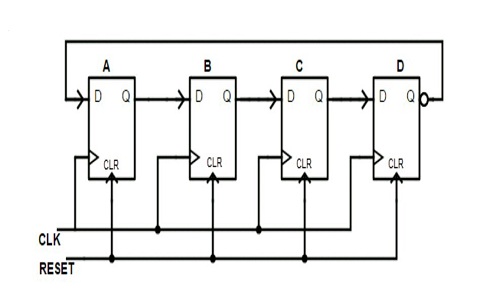
Based on the logic of the circuit structure, we can understand the working process of the above Johnson counter from a state machine perspective:
 A  B  C  D
(0, 0, 0, 0)    # Initial state
(1, 0, 0, 0)
(1, 1, 0, 0)
(1, 1, 1, 0)
(1, 1, 1, 1)
(0, 1, 1, 1)
(0, 0, 1, 1)
(0, 0, 0, 1)
(0, 0, 0, 0)    # Consistent with the initial state
Understanding the Working Process of a Sequence Summing Circuit from a State Machine Perspective
In the previous subsection, you built a simple sequence summing circuit using registers and adders to calculate 1+2+...+10. Try to list the changes in the circuit state.
Of course, this example of a Johnson counter is very different from a CPU, but if a CPU can be designed using digital circuits, it must also contain sequential logic circuits and combinational logic circuits, and therefore the working process of a CPU can also be understood from the perspective of a state machine.
Executing C Programs on a Computer
We understand the execution process of a C program from the perspective of a state machine, which essentially means executing the C program in our minds. However, computers can only execute instructions; they cannot understand the meaning of a C program, so they cannot execute code such as sum = sum + i;. So how do we get a computer to execute a C program? The answer is to translate the C program's code into a sequence of instructions that are behaviourally equivalent, and then have the computer's circuitry execute this sequence of instructions.
Compilation = Translating C Code into a Sequence of Instructions
This process has a special name in computer systems: 'compilte'.In principle, compilation can be done manually, but modern programs are very large, and manual compilation is very tedious. Therefore, compilation is usually performed by a special type of program called a 'compiler'.
Since executing C programs and executing instruction sequences can both be understood from a state machine perspective, we can also try to understand what tasks a compiler needs to perform. Let's first list the contents of the two state machines (we will not concern ourselves with the initial state here):
| C program | ISA | |
|---|---|---|
| State | ||
| Event | Executed statement | Executed instruction |
| State transition rule | Semantics of statement | Semantics of instruction |
Therefore, the compiler's job is to translate the state machine of the C program into the state machine of the ISA, or in other words, construct
make
thus,
In this context, denotes the th state of the C language state machine, and denotes the th state of the ISA state machine. In natural language, this means: The state of a C program after executing a statement is semantically equivalent to the state of the ISA after executing the instruction sequence obtained from compilation.
Specifically, after comparing the two state machines, we can see that the compiler needs to perform the following tasks:
- Translate the state of the C program into the state of the ISA, i.e.
- Map the PC of the C program to the PC of the ISA
- Map the variables of the C program to the GPR or memory of the ISA
- Translate the state transition rules of the C program into the state transition rules of the ISA, i.e., translate statements into instruction sequences.
Understand how compilers work using the example of summing a sequence of numbers
We have already provided the C program for summing a sequence of numbers and the corresponding instruction sequence. Try to understand the relationship between them from the perspective of a state machine.
Understanding how compilers work in Compiler Explorer
Specifically, click Add new... in the toolbar above the editor, select Compiler, and a window with the corresponding assembly code will pop up. The assembly code uses the x86 instruction set by default. You may not understand the specific meaning of each instruction, but by highlighting the background colour and moving the mouse, you can see the correspondence between the C code snippet and the assembly code snippet.
CPU design = Designing Digital Circuits Based on ISA
Similarly, since ISAs and digital circuits can both be understood from a state machine perspective, we can also try to understand how CPU design should be carried out. Let's first list the contents of the two state machines (we will not concern ourselves with the initial state here):
| ISA | Digital Circuit | |
|---|---|---|
| State | Sequential logic circuit | |
| Event | Execute instruction | Process combinational logic |
| State transition rule | Semantics of instruction | Logic of combinational logic circuit |
Therefore, the task of CPU design is to implement the ISA state machine using a digital circuit state machine, or in other words, construct
make
thus,
Among them, represents the th state of the CPU circuit state machine. Described in natural language, it is: the state after the ISA executes an instruction is semantically equivalent to the next state of the designed CPU under the control of combinational logic circuits.
Specifically, after comparing the two state machines, we can see that the CPU design needs to accomplish the following tasks:
- Implement the ISA states using digital circuit states, i.e., implement the PC, GPR, and memory using sequential logic circuits.
- Implement the ISA state transition rules using digital circuit state transition rules, i.e., implement the functions of instructions using combinational logic circuits.
The Relationship between Programs, ISAs, and CPUs
At this point, we can briefly review the relationship between the program, ISA, and CPU:
- Based on the functional description in the ISA manual, draw a diagram of the CPU structure -> processor microarchitecture design
- Based on the structural design, design the specific circuit -> logic design
- Develop the program -> Software programming
- Translate the program into the instruction sequence described in the ISA manual -> Compilation
- Execute the program on the CPU = Use the instruction sequence compiled from the program to control the CPU circuits to perform state transitions
- At this point, the three state machines are interconnected:
From one to infinity
You may think that the examples given above are too simple. Do modern computers really work this way? Now let's lift the veil of mystery surrounding modern computers.
We already know that by using two's complement representation, computers can use the same set of adder hardware to perform arithmetic addition and subtraction. By providing a new subtraction instruction, the program can perform subtraction operations. By using a loop implemented with a jump instruction to repeatedly execute the addition instruction, we achieve arithmetic multiplication functionality; and by repeatedly executing the subtraction instruction, we can achieve arithmetic division functionality.
The four arithmetic operations for integers have already been implemented above, and it is not difficult to implement operations for decimals. We know that in mathematics, a decimal can be represented using scientific notation. Computers can also represent decimals in a similar way, but they use binary scientific notation. Specifically, any decimal number can be represented as , where is an unsigned number represented in binary, and is a signed number represented in binary. As long as the computer records and , it is equivalent to representing the decimal number in binary form. Clearly, arithmetic operations between decimal numbers can also be converted into arithmetic operations involving and .
After implementing arithmetic operations on decimals, we can calculate basic elementary functions in a mathematical sense, including constant functions, power functions, exponential functions, logarithmic functions, trigonometric functions, and inverse trigonometric functions. Specifically, except for constant functions, the other five basic elementary functions can be calculated using power series expansions, and power series can be calculated using arithmetic operations and loops.
After implementing the calculation of basic elementary functions, all elementary functions can be calculated through a finite number of arithmetic operations between functions, exponentiation, root extraction, and composite operations. For composite operations, we can use the function call function in the program to implement them.
We can continue to differentiate and integrate the function. According to the definition of the derivative, we only need to substitute a very small , to approximately calculate the derivative of the function at a certain point. According to the definition of definite integrals, we can divide the interval being integrated into a sufficient number of segments, then approximate the function's value over the interval using its value at a point within the interval, and then calculate the Riemann sum of the function over the interval by summing the values. Of course, these are simple and intuitive computational methods. To calculate more precise derivatives and integrals on a computer, scientists have developed a series of numerical analysis algorithms.
The above calculations are all performed in the real number domain. Extending the calculations to the complex number domain is actually not difficult. Specifically, we only need to perform separate calculations on the real and imaginary components, and then apply the relevant rules to handle the imaginary unit . Although some operations in the complex number field differ from those in the real number field, as long as the calculation method can be described using mathematical language, there is always a way to convert it to the operations described above.
After supporting differentiation and integration in complex domains, we can implement various physical engines in the program, simulate various physical laws in the real world. Various formulas for mechanics, electromagnetism, optics, and thermodynamics are calculated in the program through a series of simple instructions, allowing users to experience the same physical world in the computer world. Everything we experience in the computer is achieved through computation!
Of course, to make the calculation process more efficient, modern ISAs also provide more instructions, including multiplication and division instructions, logical operation instructions (such as AND, OR, NOT, etc.), floating-point instructions, atomic instructions, and so on. For example, instead of implementing multiplication through loops, computers provide multiplication instructions and multiplier circuits, allowing programs to efficiently calculate multiplication using multiplication instructions. Some ISAs even provide instructions for directly calculating basic elementary functions, such as square root instructions and trigonometric function instructions. It is not difficult to imagine that providing the functionality to calculate these basic elementary functions at the circuit level requires careful consideration by electronic engineers.
In addition to providing richer instructions, computer architects are also committed to designing computers that can execute instructions more efficiently. For example, pipeline technology can improve the throughput of computer instruction execution, superscalar technology allows computers to execute multiple instructions in a single cycle, and cache technology improves the efficiency of computer memory access. These technologies ultimately provide computer users with increasingly faster performance experiences.
In fact, whether it was the Z3 computer in 1941, which averaged multiplication operations per second, or the supercomputer ranked first in the Top500 list in November 2024, with a peak computational capability of floating-point operations per second, their operating principles are fundamentally the same. Although the examples listed above have been highly simplified, they are sufficient to help you understand the most fundamental elements of computer systems and their interconnections. In subsequent studies, we will continue to refine these concepts, ultimately learning how to design a real CPU chip based on a real ISA and run real programs on it.